Troubleshooting
Troubleshooting: Frequent Bit Errors in the Gray-Code LSB While Higher Bits Are Fine — Contrast of Fine Code Tracks
The least significant Gray-code bit has the narrowest code elements, and with imaging readout its contrast falls fastest with gap: by the p²/λ criterion, code elements of 20 μm and 640 μm differ in sensitivity by about a thousandfold. This article simulates contrast versus gap for every bit track and the LSB margin, explains how threshold drift amplifies bit errors, and gives steps for measuring amplitude bit by bit and rechecking the gap.
A Gray-code absolute encoder occasionally reports position jumps or check errors in the field, and the faulty code value is always wrong in the least significant bit, never in the higher bits. Changing the disc sometimes helps; changing the readhead sometimes makes it worse. The advantage of Gray code is that a misread LSB is off by only one position (see the article comparing Gray code and pseudo-random code in this library), so it does not cause large jumps, but it shows up as jitter, check failures or mismatch with the incremental track. Why is the LSB always the first to fail? Because its code elements are the narrowest, and the gap sensitivity of contrast in imaging readout scales with the square of the code-element width.
Why the LSB is the most sensitive
The LSB of a reflected binary Gray code toggles every 2 positions, so its track is a square wave with a period of 4 positions and a code-element width of 2 positions; each higher bit doubles the code-element width. With an LSB code element w0 = 20 μm, the six code-element widths are 20, 40, 80, 160, 320 and 640 μm, corresponding to periods P = 2w of 40–1280 μm.
In imaging readout the shadow of the track crosses the gap g onto the detector, and there are two kinds of blur:
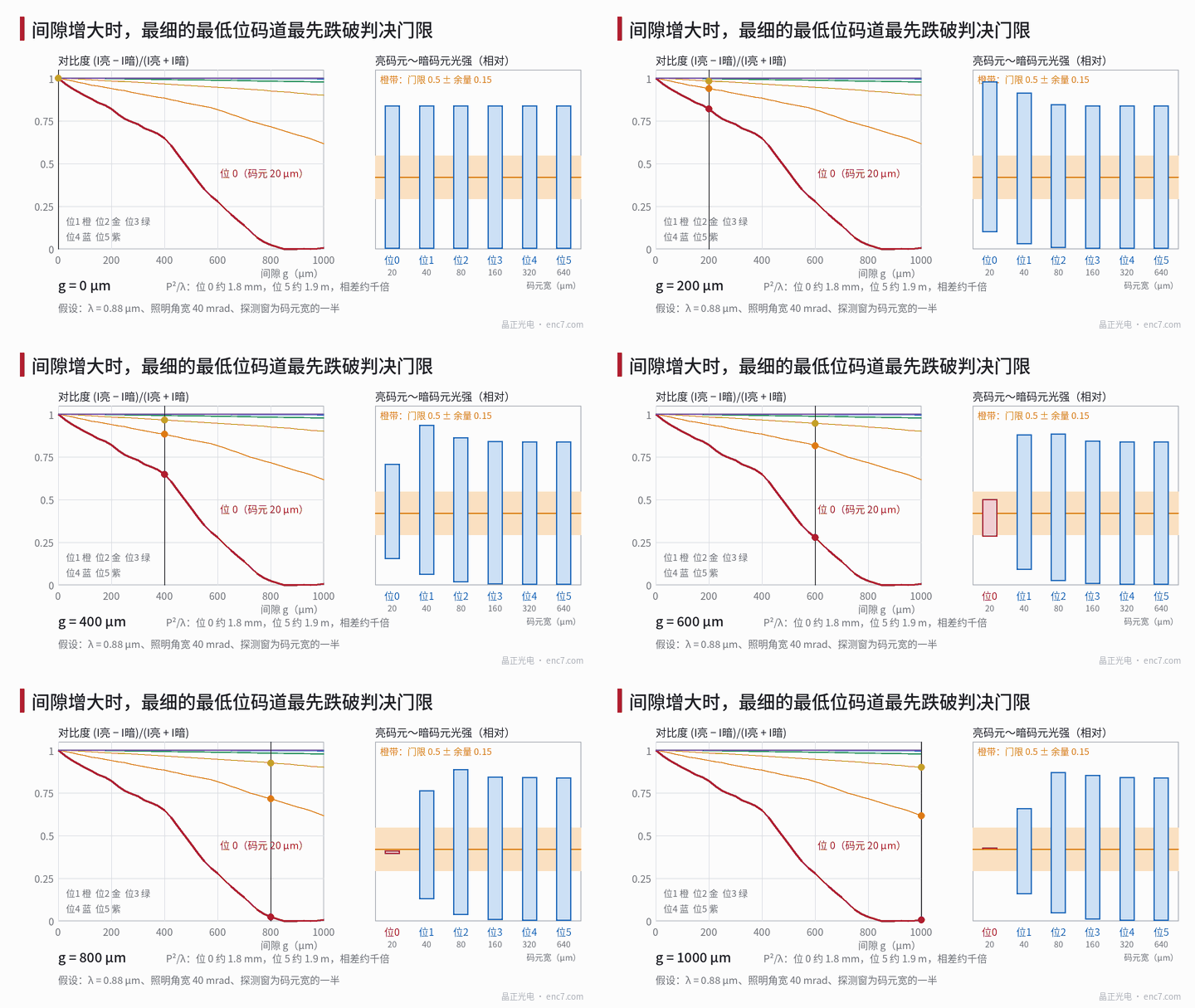
- Diffraction: characteristic scale P²/λ. At λ = 0.88 μm this is about 1.8 mm for the LSB and about 1.9 m for the most significant bit, a ratio of (1280/40)² = 1024 — “about a thousandfold”. The fundamental modulation falls as cos(πλg/P²) (derivation in the Talbot effect article of this library), reaching zero for the LSB at g = P²/(2λ) ≈ 0.9 mm.
- Penumbra: the illumination angular width Δα blurs the shadow edge by g·Δα, and the fundamental falls as sinc(g·Δα/P). At Δα = 40 mrad and g = 0.5 mm the blur is 20 μm, already equal to the LSB code-element width; this is a first-power dependence on code-element width, so LSB and MSB differ by a factor of 32.
Both mechanisms make the LSB lose contrast first, while the higher-bit tracks still cast almost sharp square shadows at the same gap.
Numerical example: contrast of each bit track
Simulation conditions (assumed): near-parallel illumination, λ = 0.88 μm, spectral width 40 nm, angular width 40 mrad; 50% duty cycle on every track; detection window half the code-element width, centred on the element; intensity normalised to 1 without pattern. After averaging over wavelength and angle of incidence, the intensity at the centre of a “bright element” and a “dark element” and the contrast C = (I_bright − I_dark)/(I_bright + I_dark) are:
| Gap g | Bit 0 bright/dark | Bit 0 contrast | Bit 1 contrast | Bit 2 contrast |
|---|---|---|---|---|
| 100 μm | 1.17 / 0.06 | 0.90 | 0.97 | 0.99 |
| 300 μm | 1.00 / 0.16 | 0.73 | 0.91 | 0.98 |
| 500 μm | 0.72 / 0.27 | 0.45 | 0.85 | 0.96 |
| 600 μm | 0.60 / 0.34 | 0.28 | 0.82 | 0.95 |
| 700 μm | 0.52 / 0.39 | 0.14 | 0.76 | 0.94 |
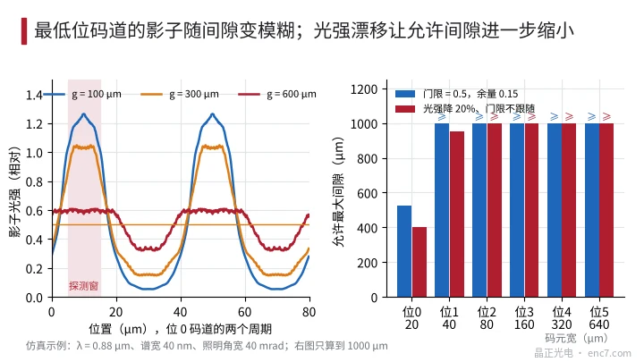
At small gaps the intensity at the centre of a bright element exceeds 1 because Fresnel diffraction at the narrow slit concentrates light towards the centre; this does not affect decoding. With the threshold at 0.5 and a margin of 0.15 required on both the bright and dark sides, the maximum allowable gap for the LSB is about 0.52 mm; bit 1 and above meet the requirement over the whole simulated range of 1 mm (Figure 2, right).
How threshold drift amplifies bit errors
Decision margin = min(I_bright − T, T − I_dark), where T is the threshold. The LSB’s bright and dark levels are already crowded around the threshold, so any drift eats its margin first:
- Intensity drift with fixed threshold: the LED’s light output falls by 20% with temperature and ageing, while the threshold stays at its initial 0.5. The bright level of the higher bits falls from about 1.0 to 0.8, still ample; for the LSB at g = 500 μm the bright level falls from 0.72 to 0.58 and the margin from 0.22 to 0.08, and at 600 μm it drops straight below the threshold. The allowable gap shrinks from about 0.52 mm to about 0.40 mm.
- Threshold offset: with comparator offset or a reference-level shift ΔT, the LSB edge moves by ΔT divided by the signal slope. The LSB has low contrast and a small slope, so the same ΔT moves its edges the most, adding zones at code transitions where the value is misread by 1.
- Noise: the zone near an edge where noise causes toggling back and forth has a width of about noise divided by slope; it is widest for the LSB, which shows up as the LSB flickering when stationary at certain positions.
The threshold should therefore track intensity: with a ratiometric threshold from a reference photodiode or a complementary track, the effect of intensity drift can be essentially cancelled.
Troubleshooting steps
- Measure amplitude bit by bit: if test points or diagnostic outputs are available, rotate slowly and record the bright and dark levels of every bit, then calculate contrast and margin relative to the threshold. Only the LSB being clearly low points to a contrast problem; all bits falling in the same proportion means checking the light source and contamination first.
- Recheck the gap: measure the actual read gap and add the axial runout and disc flatness at the read radius to obtain the maximum gap, then compare it with the allowable value. Reduce the gap by 0.1–0.2 mm with shims and re-measure; if the LSB contrast recovers as predicted, the cause is confirmed.
- Look at errors versus angle: errors concentrated in a certain angular range should be compared with the angular position of maximum gap from runout; a uniform distribution means looking at the overall gap and threshold.
- Check illumination and threshold: verify the LED type, emitting-area size and collimating lens position — a larger illumination angular width is equivalent to a larger gap; confirm that the threshold scales with intensity.
- Check the track itself: line-width deviation of the LSB code elements makes bright and dark elements asymmetric, so one side’s margin is used up first; dirt and defects on this track also show up first.
Engineering takeaways
- The gap sensitivity of each Gray-code bit scales with the square (diffraction) or first power (penumbra) of the code-element width; the LSB sets the upper gap limit.
- In design, check the maximum gap with the LSB, including axial runout, flatness and assembly errors; under the example conditions about 0.5 mm or less.
- The threshold should track intensity proportionally; otherwise a 20% intensity drop can shrink the LSB’s allowable gap by about a quarter.
- Illumination angular width is equivalent to gap: poorer collimation or an LED with a larger emitting area affects the LSB first.
- Measuring bright and dark levels bit by bit is the fastest diagnosis; when only the LSB lacks margin, check gap and illumination first — no need to change the disc first.
- In the layout, put the LSB on the outer ring: code-element width grows with radius and diffraction sensitivity falls with its square; axial runout is slightly larger at the outer ring, so include it in the calculation.
Summary
Frequent bit errors in the Gray-code LSB arise because its code elements are the narrowest and its shadow contrast falls fastest with gap: the diffraction scale P²/λ differs from that of the MSB by about a thousandfold, and the penumbra effect is also tens of times larger. Under the example conditions the LSB’s allowable gap is about 0.52 mm, and it shrinks further when intensity drifts and the threshold does not follow. Measuring levels bit by bit, rechecking the gap and using a ratiometric threshold locate and eliminate the problem.
Translated from the ENC7 Chinese technical library (article 0239). Read the Chinese original. Need a disc built to your drawing? Request a quote or see our custom encoder discs.
© Langfang Jingzheng Optoelectronic Technology Co., Ltd. All rights reserved. This article was created with AI assistance.