Troubleshooting
Troubleshooting: Interpolated Position Jitters by More than 1 LSB at Standstill — Tracing the Noise Chain Stage by Stage
Standstill position noise is σ_θ ≈ σ_v/A (electrical angle); with 2048 lines, 1 V amplitude and 1 mV noise it is about 0.1″ RMS. This article gives, stage by stage, estimation formulas and an example budget for shot noise, resistor noise, op-amp noise, ADC, LED ripple and mechanical vibration, together with the localisation sequence — lock the shaft, swap the supply, block the light, reduce intensity — and the fingerprint that identifies each source.
The encoder sits on a stationary shaft, yet the last few bits of its 23-bit absolute position keep toggling, five or six LSB peak-to-peak. The customer’s question is blunt: is the disc bad, is the readhead noisy, or is the machine vibrating? Noise travels from the light source all the way to the ADC and every stage can contribute — or it may not be noise at all, but the shaft really moving. This article gives an estimation formula for each stage and an example budget, then a field method that disconnects, substitutes and blocks the light stage by stage.
Criterion: how much noise makes the reading toggle by 1 LSB
When channels A and B each carry independent additive noise σ_v, the angle noise from the atan2 solution is (derivation in the library article on ADC resolution and interpolation resolution)
σ_θ = σ_v / A (electrical angle, rad)
To convert to mechanical angle, multiply by one signal period and divide by 2π. With 2048 lines, 1 rad electrical is about 100.7″, so 1 V amplitude and 1 mV noise give about 0.1″ RMS.
The reading covers 99.9% of samples within ±3.3σ. For no 1 LSB toggling at standstill we need 6.6σ_θ ≤ LSB, i.e. σ_v/A ≤ (2π/K)/6.6, where K is the number of LSB per signal period. With 2048 lines:
| Bits | K per period | LSB | Allowed σ_v/A |
|---|---|---|---|
| 19 bit | 256 | 2.47″ | 3.7×10⁻³ |
| 21 bit | 1024 | 0.62″ | 9.3×10⁻⁴ |
| 23 bit | 4096 | 0.154″ | 2.3×10⁻⁴ |
23 bit corresponds to a signal-to-noise ratio of about 73 dB, which an analogue front end can hardly reach directly over a bandwidth of a few hundred kHz — so first find out which source dominates.
Stage-by-stage estimate: six sources
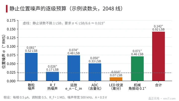
Take an example readhead (assumed): differential A = I₀ − I₁₈₀, DC photocurrent per phase I_dc = 0.5 μA, modulation m = 0.5, one transimpedance amplifier per phase with R_f = 1 MΩ, input capacitance C_in = 20 pF, op-amp voltage noise e_n = 10 nV/√Hz, noise bandwidth B = 500 kHz, hence A = 2m·I_dc·R_f = 0.5 V.
1. Shot noise. The DC of both phases contributes: σ_v/A = √(qB/I_dc)/m, q being the electron charge. Example: 8.0×10⁻⁴. It grows as 1/√I when the light level drops.
2. Feedback-resistor thermal noise. Current noise of each transimpedance stage √(4kTB/R_f); combining both phases gives 2.6×10⁻⁴ in the example. The larger R_f, the smaller it is in relative terms.
3. Op-amp voltage noise through the input capacitance. Above 1/(2πR_f·C_in) (about 8 kHz), e_n is amplified by C_in; the equivalent input current noise is about
i_n ≈ e_n·2πC_in·√(B³/3)
Example 7.3×10⁻⁴, comparable to shot noise. It grows as B^1.5, so the wider the bandwidth, the more it stands out.
4. ADC. Quantisation noise q_ADC/√12 plus the converter’s own input noise; taking 0.25 mV in the example gives 5.0×10⁻⁴. Reference-voltage noise is multiplicative: with simultaneous sampling of A and B it cancels in the ratio; with one time-multiplexed ADC the residual is (δ_B − δ_A)·sin2θ/2.
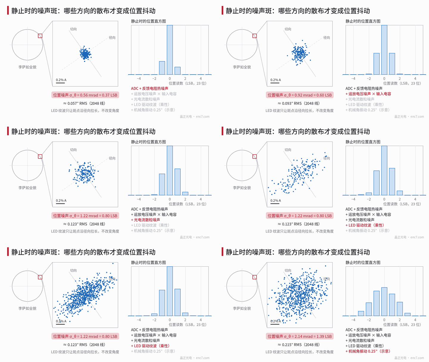
5. LED drive ripple. Ripple r scales A and B together and does not change the angle by itself; on the Lissajous figure it only stretches the spot radially (see Figure 1). It enters the angle only via an uncancelled DC component proportional to light intensity:
δθ = r·(ε_B·cosθ − ε_A·sinθ)
ε_A and ε_B are the relative offsets of the two channels. In a differential design with 2% residual offset and 0.5% RMS ripple this is only about 1.0×10⁻⁴; but with single-ended signals whose DC is removed against a fixed reference, the DC-to-amplitude ratio is 1/m = 2, and the same 0.5% ripple becomes about 1% noise — about 1″, far above all the other terms.
6. Mechanical vibration. Real angular vibration of the shaft appears directly in the reading and stretches the spot tangentially on the Lissajous figure. Assuming an angular vibration amplitude of 0.1″, the RMS value is about 0.071″.
The budget is summarised in Figure 2: the electronic terms total about 0.123″; adding mechanical vibration gives about 0.142″ RMS, i.e. 0.92 LSB, and a ±3.3σ peak-to-peak of about 6 LSB — consistent with the symptom described at the start. To stop toggling at 23 bit, σ must fall to about 0.023″, which is very hard with the analogue front end alone; usually digital filtering narrows the equivalent bandwidth at standstill.
Field localisation: disconnect, substitute, block the light
Order the steps from least to most disassembly effort:
- Lock the shaft, disable the drive. Clamp the shaft or remove servo enable (mind vertical-axis safety). If the noise drops markedly and the tangentially stretched spot disappears, it is mechanical vibration or servo hold dithering, and the readhead is fine. Then take a spectrum of the standstill position and check whether lines fall on structural resonances, mains frequency or PWM frequency.
- Power the LED from another supply. Replace the original driver with a battery-powered linear constant-current source. If the noise drops, driver ripple is leaking in through the DC component — check this especially in single-ended designs.
- Block the light. Cover the reading window or switch off the LED and measure the noise voltage σ_dark on A and B; this is the electronic noise floor. The square root of the difference of squares between the lit σ_light and σ_dark is the shot-noise plus ripple term. Open the constant-light loop first, otherwise the loop drives the LED to maximum once the light is blocked.
- Short the ADC inputs. What remains is ADC and reference noise, which can be compared with the data sheet.
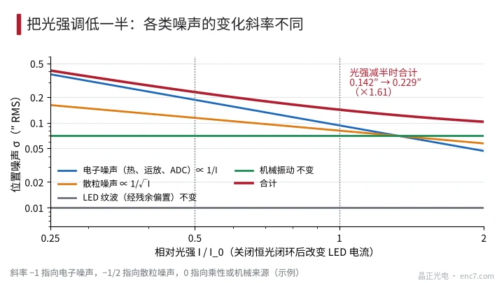
- Halve the light intensity. If total noise roughly doubles (2×), electronic noise dominates; about 1.41×, shot noise dominates; essentially unchanged, a multiplicative or mechanical source (see Figure 3). In the example readhead, halving the light raises noise from 0.142″ to 0.229″, about 1.61×, between the two — consistent with the budget.
- Change the standstill position. Measure σ at 8 positions within one signal period. Additive noise does not depend on position; a variation once per period points to ripple leaking via offset; four times per period with a maximum near 45° points to reference noise with time-multiplexed sampling.
The disc acts mainly through amplitude: contamination, haze in the transparent areas or an oversized gap all lower A, and the fixed electronic noise is amplified in proportion. So when the same readhead jitters differently on different discs, compare the amplitudes first rather than suspecting noise.
Engineering notes
- First convert the symptom into σ_v/A: no 1 LSB toggling at 23 bit and 2048 lines requires about 2.3×10⁻⁴, i.e. about 73 dB.
- Shot noise σ_v/A = √(qB/I_dc)/m; raising photocurrent and modulation is more effective than picking op-amps.
- Op-amp voltage noise through the input capacitance grows as B^1.5; use only as much bandwidth as needed and minimise detector and trace capacitance.
- Single-ended designs with DC removal against a fixed reference are extremely sensitive to LED ripple: 0.5% ripple can cause about 1″ of jitter; switch to differential signals or a regulated current drive.
- Lock the shaft, swap the supply, block the light, short the ADC, halve the intensity — localise in this order, changing only one variable per step.
- The shape of the Lissajous spot is a quick criterion: a round spot is additive noise, radial stretching is multiplicative, tangential stretching is real motion.
Summary
Interpolated position jitter at standstill means, in essence, that σ_v/A is not small enough — or that the shaft itself is moving. Estimate shot noise, resistor thermal noise, op-amp voltage noise, ADC, LED ripple and mechanical vibration term by term, then run comparison tests in the order lock shaft, swap supply, block light, reduce intensity to find the dominant term; the different scaling with light intensity and standstill position is the cheapest fingerprint for telling the sources apart.
Translated from the ENC7 Chinese technical library (article 0222). Read the Chinese original. Need a disc built to your drawing? Request a quote or see our custom encoder discs.
© Langfang Jingzheng Optoelectronic Technology Co., Ltd. All rights reserved. This article was created with AI assistance.