Troubleshooting
Troubleshooting: Lissajous Ellipse Tilt Swings Once per Revolution — Pitch Mismatch from Eccentricity

Eccentricity makes the read radius vary once per revolution, so the phase difference between the A/B detection fields swings as 2π(n + 1/4)(e/r)cosθ — about ±2.3° for r = 10 mm, e = 20 μm, n = 3. This article explains how it differs from static phase error and how it affects self-calibration, and gives diagnosis by angle-segmented fitting and small radial shifts.
Viewing A and B in X-Y mode on the oscilloscope, within one revolution the Lissajous figure first tilts towards 45°, then becomes a circle, then tilts towards 135° — back and forth once per revolution. An ellipse fit to a whole revolution of data shows a phase error of only a few tenths of a degree, yet after correction the interpolation error still undulates with rotation angle. The sources of a static tilted ellipse and how to track them down are covered in the tilted-ellipse article of this series, which gives the formula for phase error caused by a read-radius error. This article discusses its dynamic version: eccentricity makes the read radius vary once per revolution, and the phase error swings with it.
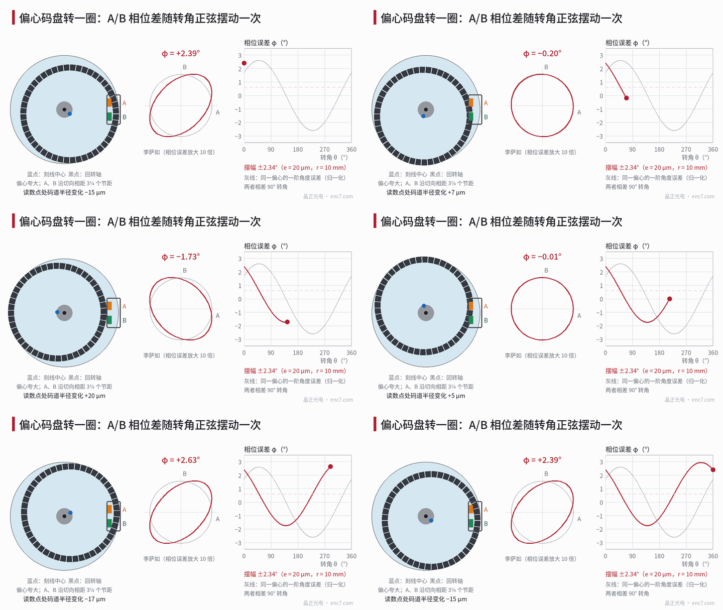
Model: the read radius swings, and the inter-field phase difference swings with it
In a readhead with separate detection fields, the A and B fields are (n + 1/4) design pitches p apart tangentially, n being an integer. When the graduation centre is offset from the axis of rotation by e, the distance from the read point to the graduation centre is r − e·cos(θ − θ_e), and the local pitch changes in the same proportion, so the deviation of the A–B phase difference from 90° is
φ(θ) = φ0 + 2π·(n + 1/4)·(e/r)·cos(θ − θ_e)
where φ0 is the static phase error (readhead mounting radius, azimuth, circuit delay etc.) and θ_e is the direction of eccentricity. Example: r = 10 mm, e = 20 μm, n = 3 give a swing of 2π × 3.25 × 0.002 ≈ 0.041 rad, about ±2.3°.
Eccentricity also rotates the direction of the lines at the read point by ψ ≈ (e/r)·sin(θ − θ_e). If the A and B fields are also offset radially by Δy, an extra term 2π·Δy·ψ/p appears: with Δy = 0.2 mm and 2048 lines (p ≈ 30.7 μm) its amplitude is about 4.7°. This term varies as sin and is 90° of rotation apart from the pitch-mismatch term; the combined swing is the vector sum of the two.
Both mechanisms repeat once per revolution and are independent of speed; phase error caused by circuit delay, by contrast, grows with frequency and does not vary with rotation angle, so it can be ruled out by repeating the measurement at two speeds.
How it differs from static phase error
Static phase error φ0 is constant over the revolution and a single ellipse fit removes it. The part that swings once per revolution cannot be removed that way:
- The interpolation error is about φ/2, twice per period. With φ swinging once per revolution, the 2N-th order component is modulated at order 1, producing sidebands at orders 2N ± 1 in the error spectrum.
- If self-calibration uses parameters averaged over a whole revolution, the residual still has half the swing: about ±2.1″ for 2048 lines in the example above (1° of phase error corresponds to about 0.9″).
- If calibration is done only once at a single angle, the residual at other angles can reach up to twice the swing (when the calibration point happens to be at an extreme), about 3.6″ in the example above.
- If an online recursive correction has a time constant shorter than one revolution, it can follow the swing at low speed but not at high speed, so the interpolation error appears to change with speed.
Switching to a correction table of 36 angle segments with interpolation over rotation angle reduces the residual in the example to about 0.2″ (see Figure 2, right). This shows that the problem is not the correction algorithm but that the parameters themselves vary with rotation angle.
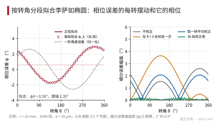
Diagnosis: segmented fitting by rotation angle
- Segmented acquisition: using Z as the angle reference, turn at constant speed for more than one revolution and divide the A and B samples by rotation angle into K segments (e.g. 36), each containing several tens of signal periods.
- Fit segment by segment: fit an ellipse to each segment to obtain φ_k, then fit φ_k = φ0 + a·cosθ_k + b·sinθ_k; the swing is √(a² + b²). Only when the swing clearly exceeds the repeatability of the segment fits (typically achievable to the order of 0.1°) is it judged to be a once-per-revolution swing.
- Check the phase: compare the phase of the swing with that of the first-order angular error, which can be obtained by calibration against a reference encoder or from the reading difference of two diametrically opposed readheads. If they are about 90° of rotation apart, the main cause is pitch mismatch; if in phase or in antiphase, the main cause is line-direction rotation combined with radial offset of the two fields.
- Calibrate with a small radial shift: move the readhead radially by a known Δr (e.g. 20 μm); the change of static φ0, Δφ0 = 2π(n + 1/4)·Δr/r, gives the sensitivity k_r = Δφ0/Δr. In the example above, 20 μm corresponds to 2.34°, k_r ≈ 0.117°/μm. The eccentricity estimate e ≈ swing ÷ k_r is then compared with the track runout measured by dial indicator or with the e/r first-order error; agreement confirms the diagnosis.
- Repeat at two speeds: the swing does not change with speed, which rules out circuit delay and lag of the online correction.
Engineering notes
- If the Lissajous tilt swings once per revolution, check eccentricity first: the swing is about 2π(n + 1/4)·e/r, about ±2.3° for r = 10 mm, e = 20 μm, n = 3.
- The larger the number of periods n between the A/B fields, the higher the sensitivity; an array with four phases interleaved within one period shows only about ±0.18° at the same eccentricity.
- Derive self-calibration parameters from whole-revolution data; for high accuracy build a table segmented by rotation angle — do not calibrate at a single position only.
- A swing phase 90° apart from the first-order angular error points to pitch mismatch; in phase points to radial offset of the two fields plus line-direction rotation.
- Measuring Δφ0 with a 20 μm radial shift converts the swing directly into eccentricity without knowing n.
- The real cure is centring: halve the eccentricity and both the swing and the 2N ± 1 sidebands are halved.
Summary
A Lissajous ellipse tilt that swings once per revolution means eccentricity is making the read radius and local pitch vary once per revolution, and the phase difference between the detection fields swings with it. Unlike static phase error, it cannot be removed by a correction averaged over a revolution, and a correction calibrated at only one position makes it worse. Measuring swing and phase by segmented fitting over rotation angle and converting the swing into eccentricity with a radial-shift calibration confirms the source; centring and readheads with interleaved arrays are the fundamental remedies.
Translated from the ENC7 Chinese technical library (article 0234). Read the Chinese original. Need a disc built to your drawing? Request a quote or see our custom encoder discs.
© Langfang Jingzheng Optoelectronic Technology Co., Ltd. All rights reserved. This article was created with AI assistance.