Troubleshooting
Troubleshooting: Lissajous Ellipse with Axes Along the Coordinates — Unequal A/B Amplitude
A Lissajous figure that becomes an ellipse with major axis along a coordinate axis means unequal A and B amplitudes; relative difference δ produces interpolation error twice per period of about δ/2 rad (about 1″ for 2% at 2,048 lines). This article analyses disc-side and assembly-side sources, how to compute δ from the two axis extents, and separation tests by swapping channels, moving radially and fine-tuning roll.
The Lissajous figure is an ellipse whose major and minor axes lie exactly along the A and B coordinate axes, with no tilt: phase between the channels is normal, but one amplitude is smaller than the other. Mismatched circuit gain is a common cause, yet the disc and the assembly can produce the same symptom and swapping the electronics will not remove it. This article first gives how to read δ and convert to error, then catalogues disc-side and assembly-side sources, and finally separates them with a few simple actions.
How large is the error, and how to read δ
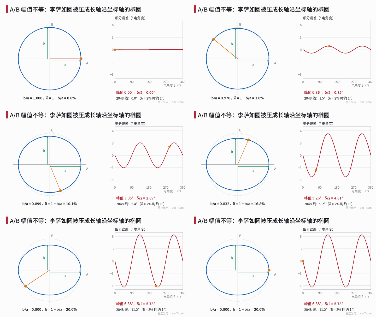
Let A = a·cosθ, B = b·sinθ, relative amplitude difference δ = 1 − b/a. The atan2 error occurs twice per signal period; its peak is exactly arcsin((a − b)/(a + b)), about δ/2 rad for small values. At δ = 2% the peak is 0.0101 rad, about 1.0″ at 2,048 lines; at δ = 20% it is 6.38°, about 11% above the δ/2 value of 5.73°.
Read δ from the scope using the extents along the two axes, not the major/minor axes of the ellipse:
a = (X_max − X_min)/2, b = (Y_max − Y_min)/2, δ = 1 − b/a
That stays accurate even with simultaneous DC offset and phase error, because A’s maximum is always a regardless of phase; once the ellipse tilts, the axis ratio mixes in phase error.
Allowed δ depends on line count. Allocating 1″ to amplitude difference alone: about 2.0% at 2,048 lines, 4.8% at 5,000, 9.7% at 10,000. For the same arc-second budget, higher line count actually tolerates more amplitude mismatch.
Disc-side sources
The disc lines are shared by both channels; for the disc to make the two amplitudes differ, the two channels must not see the same pattern.
- Two-phase detection fields at different radial positions on the track. Some readheads stack A and B fields in radial rows. If the track is radially non-uniform the two rows get different modulation: e.g. outer duty cycle 0.45, inner 0.50, fundamental by sin(πD) differs by only about 1.2%; chrome OD 2 versus OD 3 changes leakage from 1% to 0.1% and modulation by about 0.9%. Rounded, narrowed line ends at the track edges also penalise the row nearer the edge.
- Local OD or line-width difference. When A and B are separated tangentially, the two fields see regions several periods apart at any instant; local film-thickness or line-width variation makes δ change with angle rather than stay constant.
These are typically only ~1% and usually within budget alone; δ of several percent or more more often points to assembly and the readhead itself.
Assembly-side and readhead-side sources
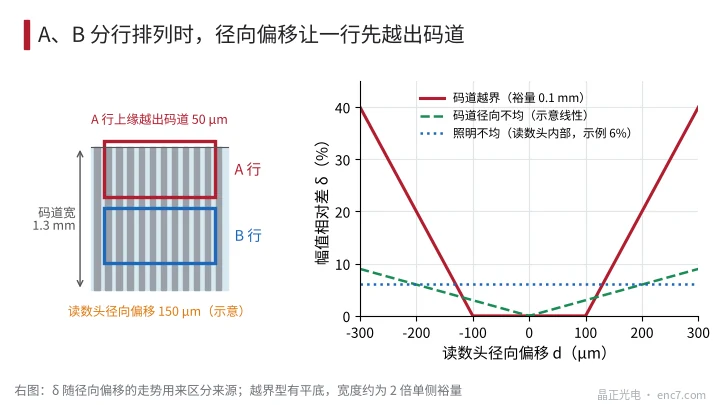
Radial offset drives one row off the track. Example (assumed): each row 0.5 mm high, 0.1 mm apart, track width 1.3 mm, unilateral margin 0.1 mm. At 150 μm radial offset the upper edge of row A leaves the track by 50 μm, amplitude drops 10%, δ = 10%, peak interpolation error about 5.3″ at 2,048 lines. δ versus offset is “flat bottom then steep rise”: zero within ±0.1 mm, then +2% per 10 μm beyond (Figure 2). With eccentricity, δ varies once per revolution.
Roll makes the two rows see different gaps. Readhead roll γ about the tangential axis with row centres Δy apart gives gap difference Δy·γ, so δ ≈ |S|·Δy·γ, S the relative slope of the amplitude–gap curve. At Δy = 0.6 mm, γ = 5 mrad the gap difference is 3 μm: about δ ≈ 2.5% at 10,000 lines, nominal gap 25 μm (S ≈ −0.84%/μm), and about 1.1% at 5,000 lines, 150 μm.
Illumination and detectors. Unequal illuminance on the two rows is a common internal readhead source. Gaussian spot σ = 1 mm, row centres at ±0.3 mm, spot centre offset 0.1 mm: illuminance ratio ≈ 1.06, δ ≈ 6%. It moves with the whole readhead; radial readhead motion does not change δ.
Circuit gain. Mismatched amplifier gains are independent of the disc but must be ruled out first.
Separation tests
- Swap channels: swap A and B into the interpolator (or swap the two scope channels). If the smaller one follows the channel, it is circuit gain; if it follows the signal, it is optics, disc or assembly.
- Radial move: shift the readhead radially in steps with shims or a slotted hole and record δ. Flat bottom then steep rise means track overrun; flat-bottom width ≈ 2× unilateral margin. Slow linear change points to radial track non-uniformity; essentially no change means internal readhead (illumination, detectors).
- Full revolution: segment δ by Z. Constant → static cause; once per revolution → eccentricity plus overrun; only at certain angles → local film or line width.
- Roll tweak: add a thin shim under one side of the readhead; if δ changes linearly, the two rows see different gaps — correct mounting-face parallelism.
- Swap disc: if practical, change to another disc of the same batch or a reference disc; if δ follows the disc, go back to radial uniformity and line-width consistency of the disc.
Figure 3 summarises the characteristic responses of five source classes under these actions. Only readheads with A and B in radial rows show overrun and roll problems; when A and B are interleaved in one row those two classes essentially do not occur.

Engineering notes
- Compute δ from the X and Y extents: δ = 1 − (Y_max − Y_min)/(X_max − X_min), immune to offset and phase error.
- Peak interpolation error ≈ δ/2, exactly arcsin((a − b)/(a + b)); 2% ≈ 1″ at 2,048 lines.
- For rowed structures, design track width as “total height of both rows + 2 × (radial mount tolerance + eccentricity)”, or overrun shows up directly as amplitude imbalance.
- Check readhead mounting-face roll by |S|·Δy·γ; tighter at fine pitch and small gap.
- Disc-side line-width and OD radial uniformity typically affect ~1%, but they stack on other sources — incoming inspection should measure one point on each side of the track.
- Rule out the circuit by channel swap first, then radial move and roll tests — do not reverse the order.
Summary
An ellipse with axes along the coordinates means unequal A/B amplitudes, with error twice per period of about δ/2. Disc-side sources are the two phase fields seeing inconsistent track regions, usually small; assembly-side radial overrun and roll matter more on rowed structures. Read δ from the two axis extents, then separate circuit, readhead, assembly and disc contributions by channel swap, radial move, full revolution and roll tweak in that order.
Translated from the ENC7 Chinese technical library (article 0206). Read the Chinese original. Need a disc built to your drawing? Request a quote or see our custom encoder discs.
© Langfang Jingzheng Optoelectronic Technology Co., Ltd. All rights reserved. This article was created with AI assistance.