Troubleshooting
Troubleshooting: Lissajous Figure Becomes a Tilted Ellipse — A/B Phase Error Causes and Checks

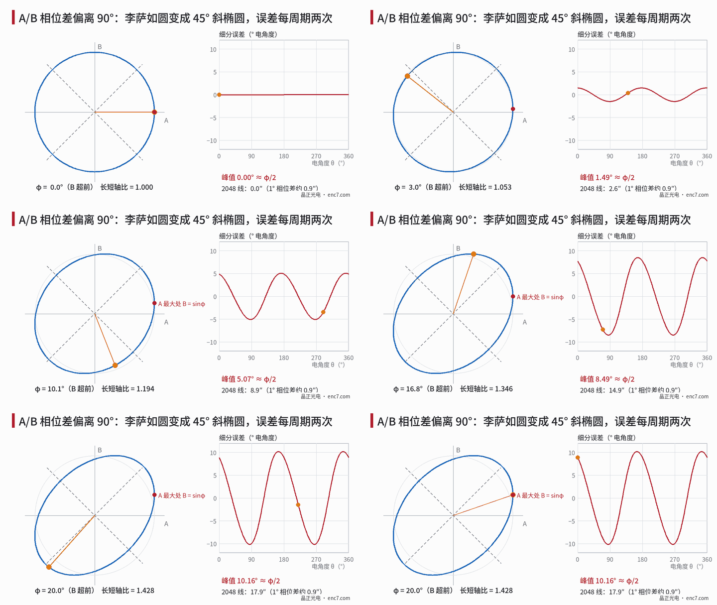
A Lissajous figure that becomes a 45° tilted ellipse means the A/B phase difference deviates from 90°; the interpolation error occurs twice per period with a peak of about φ/2. This article derives the phase error caused by read-radius deviation, Δφ = 2π·(n + 1/4)·Δr/r, compares azimuth and circuit-delay sources, and gives formulas for reading the phase difference from the ellipse and a troubleshooting order.
In oscilloscope X-Y mode, A and B trace not a circle but a tilted ellipse with its major axis at 45° or 135°: the phase difference between the two channels has deviated from 90°. This defect does not change amplitude and is hard to spot from the waveforms alone, but it feeds straight into interpolation error. This article answers three questions: how large the error is; where in the disc and assembly the phase difference comes from; and how to read φ accurately from the ellipse and in what order to troubleshoot.
How large is the phase error
Let A = cosθ, B = sin(θ + φ), with φ the deviation from 90°. After removing a constant zero shift, the difference between atan2(B, A) and θ is approximately:
Δθ ≈ (φ/2)·cos2θ
Twice per signal period, with a peak of about φ/2 (electrical angle). Numerical check: at φ = 20° the peak is 10.16°, so the small-angle approximation still holds here. At 2,048 lines one signal period is about 632.8″ and 1 rad electrical is about 100.7″, so 1° of phase error produces about 0.9″ of interpolation error.
Source 1: pitch mismatch from read-radius deviation
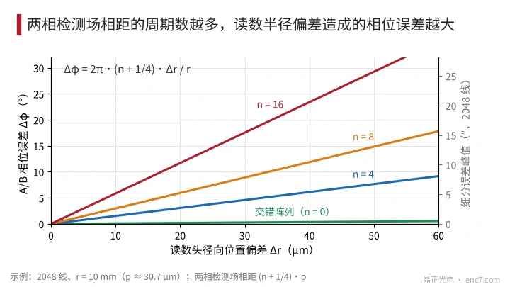
The A and B detection fields on the readhead are spaced (n + 1/4) design pitches apart along the measuring direction, with n an integer. Disc lines are radial, so when the readhead is mounted at radius r + Δr the local pitch it sees becomes p·(1 + Δr/r), and the phase difference between the two fields deviates accordingly:
Δφ = 2π·(n + 1/4)·Δp/p ≈ 2π·(n + 1/4)·Δr/r
where Δp/p is the relative pitch mismatch. For large n it is often written Δφ ≈ 2π·n·Δp/p. Example: 2,048 lines, r = 10 mm (p ≈ 30.7 μm):
| Field spacing | Δr = 10 μm | Δr = 30 μm | Δr = 50 μm |
|---|---|---|---|
| Interleaved array (n = 0) | 0.09° | 0.27° | 0.45° |
| n = 4 | 1.5° | 4.6° | 7.7° |
| n = 8 | 3.0° | 8.9° (≈7.8″) | 14.9° |
| n = 16 | 5.9° | 17.6° | 29.3° |
The conclusion is direct: the more periods separating A and B, the more sensitive to read radius; arrays with all four phases interleaved within one period are hardly affected (Figure 2). The same mechanism has two variants: a read radius or line count on the disc drawing that differs from the readhead design value is equivalent to a large fixed Δr; and eccentricity e makes the read point wander radially by Δr = e·cosθ, so phase error varies once per revolution — about ±5.9° for n = 8, e = 20 μm, r = 10 mm — and the ellipse tilts and straightens over one revolution.
Source 2: azimuth and stacked-row layouts
If the A and B detection fields are stacked in rows along the line direction (radially), separated by Δy, then when the readhead rotates by azimuth ψ relative to the lines an extra phase difference appears between the fields:
Δφ = 2π·ψ·Δy/p
For p = 30.7 μm, Δy = 0.5 mm and ψ = 1 mrad this is about 5.9°, while amplitude hardly changes. A tangential offset Δt of the readhead from its design position is equivalent, for radial lines, to an azimuth of Δt/r. Amplitude tolerance for azimuth is covered in the library article on azimuth alignment; for stacked-row designs the tolerance is set by phase error and is much tighter.
Source 3: circuit delay (rule out first)
If the filters or traces of the two analogue channels differ in delay by Δτ, the phase error is Δφ = 360°·f·Δτ, where f is the signal frequency. At 2,048 lines and 3,000 r/min, f ≈ 102 kHz and Δτ = 20 ns produces about 0.74°; doubling the speed doubles the error. It has nothing to do with the disc but is the easiest to rule out with a speed test.
Reading the phase difference from the ellipse
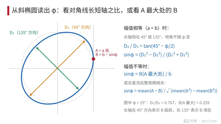
With equal amplitudes the ellipse’s major axis is always at 45° or 135°; tilt does not change with φ — φ shows in the lengths of the two diagonals. With the 45° diameter D₁ and the 135° diameter D₂:
D₂/D₁ = tan(45° − φ/2), sinφ = (D₁² − D₂²)/(D₁² + D₂²)
A major axis at 45° means B leads; at 135° B lags. At φ = 15°, D₂/D₁ ≈ 0.767; at φ = 1° the difference is only about 1.7% and hard to read with cursors.
With unequal amplitudes the major axis departs from 45°, and tilt depends on both amplitude ratio and φ, so tilt should not be converted directly. Two more reliable readings (Figure 3):
- Tangent-point method: when A reaches its maximum a, B = b·sinφ, so sinφ = B(at A max)/b;
- Correlation method: capture an integer number of periods, remove DC, then sinφ = mean(A·B)/√(mean(A²)·mean(B²)) — the correlation coefficient of the two signals, computable with scope maths or exported data, resolving below 1°.
Troubleshooting order
- Quantify: measure φ and its sign by the correlation method, convert to interpolation error, and check against the budget.
- Change speed: measure at low and high speed. If φ scales with speed, check channel delay and filter matching.
- Turn a full revolution: measure φ in segments referenced to Z. Variation once per revolution means eccentricity combined with field spacing n — check centring first.
- Check radial position: compare the disc drawing’s read radius with the readhead mounting radius. If possible, move the readhead ±20 μm radially and measure dφ/dr; the equivalent (n + 1/4) = (r/2π)·dφ/dr tells you whether the readhead uses split fields.
- Sweep azimuth: rotate the readhead by small angles; if φ changes linearly, the detection fields are stacked in rows — adjust for minimum quadrature error, not maximum amplitude.
- Check matching: once the above are ruled out, check disc line count and read radius against readhead design values, and the readhead’s own field spacing.
Engineering notes
- Peak interpolation error of a tilted ellipse is about φ/2: at 2,048 lines, about 0.9″ per 1° of phase error.
- For split-field readheads, allocate read-radius tolerance by Δφ = 2π·(n + 1/4)·Δr/r; at n = 8 and r = 10 mm, 30 μm deviation already gives about 9°.
- Interleaved arrays are insensitive to read radius and better suited to small radii and loose assembly tolerances.
- Do not read φ from ellipse tilt: with equal amplitudes tilt is always 45°; use diagonal lengths or the correlation coefficient.
- φ varying with speed → check circuits; with angle → check eccentricity; with azimuth → check stacked rows. Three steps separate the sources.
- Read radius and line count on the disc drawing must be checked item by item against readhead design values; if they disagree, no adjustment can compensate.
Summary
A tilted Lissajous ellipse corresponds to A/B phase deviating from 90°, with interpolation error twice per period and peak about φ/2. The main disc- and assembly-side source is pitch mismatch from read-radius deviation, with sensitivity proportional to the number of periods between the phase fields; azimuth matters a lot for stacked-row designs; circuit delay varies with speed. Read φ accurately with the correlation method, then check speed, angle, radial position and azimuth in turn to locate the cause.
Translated from the ENC7 Chinese technical library (article 0205). Read the Chinese original. Need a disc built to your drawing? Request a quote or see our custom encoder discs.
© Langfang Jingzheng Optoelectronic Technology Co., Ltd. All rights reserved. This article was created with AI assistance.