Troubleshooting
Troubleshooting: Reflective Readout Contrast Only Half of Expected — Back-Surface Reflection of the Substrate

When a glass disc is used for reflective reading, light entering the clear gaps reflects off the back face or parts below the disc, shifts sideways by 2t·tanθ′ and exits again through the clear gaps, forming a background in anti-phase or offset phase relative to the main fringes. This article derives the effect of back reflectance and lateral shift on modulation — an equivalent reflectance of about 0.4 is enough to halve it — and gives troubleshooting steps including a blackening comparison and a tilt test.
A glass disc is used with a reflective readhead. Estimated from the chrome-line reflectance and the glass surface reflectance, modulation should be at a certain level, but the measured value is only about half; and the same batch of discs gives different results on different hubs. The pattern on the top surface is fine; the problem lies in the light that passes through the clear gaps: it reflects back from the glass back face or from parts below the disc, comes out through the gaps again, and overlays the main fringes. This article works out where that light goes, how much it affects modulation, and how to confirm and fix it quickly. Ghosts between components inside the readhead are covered in the library article on stray light; only the disc-substrate path is discussed here.
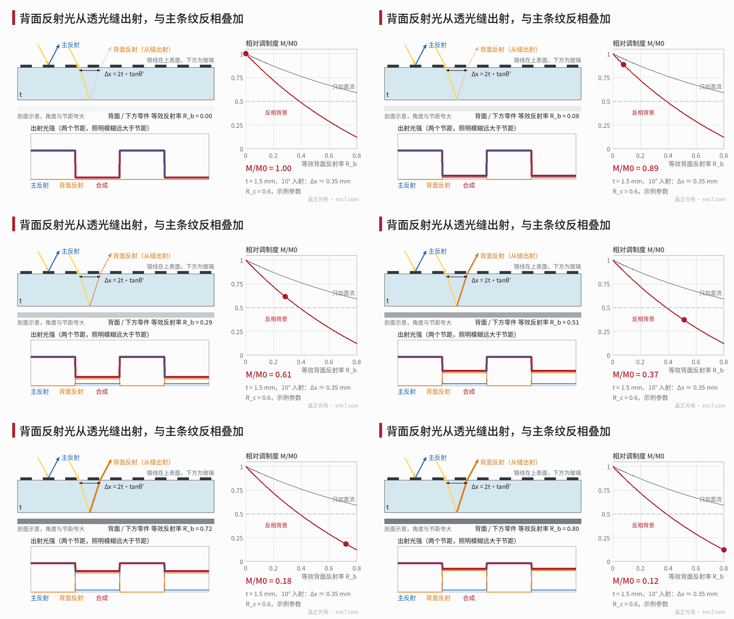
Light path: where the back-reflected light goes
The chrome lines are on the top surface, facing the readhead. Illumination strikes the disc at incidence angle θ: light falling on chrome is reflected (reflectance R_c, about 0.6 for bare chrome in the near infrared) — this is the main signal. Of the light falling on clear gaps, about 4% reflects from the top surface and the rest enters the glass at refraction angle θ′, where sinθ = n·sinθ′. It reflects from the back with equivalent reflectance R_b and, on returning to the top surface, has shifted laterally by
Δx = 2t·tanθ′
where t is glass thickness and n the refractive index. For soda-lime glass with n = 1.52, t = 1.5 mm and θ = 10°, θ′ ≈ 6.56° and Δx ≈ 0.35 mm, equal to 17.25 periods of a 20 μm pitch.
Light returning to the top surface can only exit through the clear gaps; the part landing on the back of the chrome lines is reflected down again (bare chrome seen from the glass side reflects about 0.44), making several round trips. With an illumination angular width Δθ, the round trip also blurs the back image into a band of width b ≈ 2t·Δθ/n: at Δθ = 20 mrad, b ≈ 39 μm, already larger than a 20 μm pitch.
Model: modulation in two limits
Output intensity = main reflection + back component. The back component equals “clear-gap pattern × shifted and blurred incident pattern”, added as incoherent intensities (an LED’s coherence length is only of order 20 μm, far less than the 3 mm round trip).
Blur much larger than pitch (b ≫ p): the returning light is already uniform below the top surface and exits only through the clear gaps — bright on the gaps, exactly in anti-phase with the main signal, which is bright on the chrome. Counting a single round trip, the relative modulation is
M/M0 = (1 − k)/(1 + k′), k = T²·R_b /[2(R_c − R_f)], k′ = T²·R_b /[2(R_c + R_f)]
where R_f ≈ 0.04 is the top-surface reflectance and T ≈ 0.96 the top-surface transmittance. With R_b = 0.04 (glass back face only), M/M0 ≈ 0.94; at R_b ≈ 0.42 it drops to 0.50; including multiple round trips, about 0.46 for the same R_b.
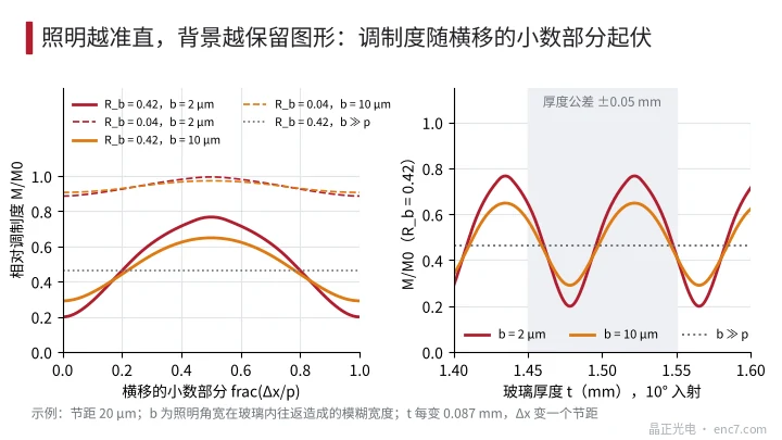
Blur much smaller than pitch (b ≪ p): the back component retains the pattern, and its overlap with the clear gaps varies with the fractional part of Δx/p; the phase difference between background and main fringes is no longer 180° but varies with thickness and incidence angle. With R_b = 0.42 and b = 2 μm, M/M0 ranges from 0.20 (fractional part 0, returning light exactly on the gaps) to 0.77 (fractional part 0.5). Every 0.087 mm of thickness change shifts Δx by one pitch; a ±0.05 mm thickness tolerance is enough to put discs from the same batch at different points on the curve, appearing as unit-to-unit variation (Figure 2).
Another case must be distinguished: readheads with source and detector in the same plane projecting divergent light directly. Here the back component comes from a deeper virtual source with a different projection magnification from the main fringes; on the detector plane it no longer has the same period as the detector array and appears mainly as DC. In this case R_b = 0.42 only reduces M/M0 to about 0.75; halving it needs a brighter reflector.
| Equivalent R_b | b ≫ p | b ≪ p (varies with thickness) | DC only |
|---|---|---|---|
| 0.04 | 0.94 | 0.89–1.00 | 0.97 |
| 0.20 | 0.72 | 0.53–0.93 | 0.87 |
| 0.42 | 0.46 | 0.20–0.77 | 0.75 |
| 0.60 | 0.29 | 0.01–0.59 | 0.67 |
(R_c = 0.6, pitch 20 μm, b = 2 μm for the b ≪ p column; all examples.)
So the 4% reflection from the glass back face alone costs only a few percent of modulation; “only half left” usually means there is a bright surface below the disc: a polished hub face, a back side with a reflective coating, light-coloured plastic parts or bare copper pads.
Troubleshooting steps
- Rule out other causes first: check film orientation (is the chrome facing the readhead), whether the chrome has a low-reflectance blackened layer, and whether the read gap is within design — each of these can also cut contrast severalfold.
- Look at the dark level: with the disc stationary and a clear gap aligned with the detector window, measure the ratio of reflected intensity to that at a chrome line. It should be close to R_f/R_c ≈ 0.07; a clearly higher value means light is coming back through the gaps.
- Blackening comparison: apply black tape, black paint or black velvet to the back face under the track and remeasure modulation. If it recovers to the expected value, the back path is confirmed. Note that tape applied across an air gap still leaves the 4% of the glass face.
- Tilt test: tilt the readhead about 1°; Δx changes by about 35 μm, nearly two pitches. If modulation fluctuates noticeably, illumination is collimated and the background retains the pattern; if essentially unchanged, it is a uniform anti-phase background.
- Analyse unit-to-unit variation: modulation correlated with glass thickness points to the b ≪ p case; correlated with hub batch or surface treatment points to a bright surface below.
Engineering notes
- Treat the back face of a reflective glass disc as an optical surface: an absorbing back coating or a blackened hub can bring R_b down to a few percent.
- An anti-reflection coating on the back only deals with the glass face’s own ~4%; it does nothing for bright parts below.
- An equivalent R_b of about 0.4 halves modulation; do not put polished metal, light-coloured plastic or bare pads directly below the track.
- With well-collimated illumination, modulation is thickness-sensitive with a period of p/(2tanθ′), about 0.087 mm in the example; evaluate batch spread against thickness tolerance.
- To push the back-reflected light out of the field of view, Δx must exceed the illumination spot and detector window size: a 1 mm window with 1.5 mm glass needs about 29° incidence, generally impractical — blackening is more reliable.
- Metal discs, or structures with an absorbing layer under the chrome, have no such light path and can be preferred when contrast requirements are high.
Summary
In reflective reading, light passing through the clear gaps reflects from the back face or parts below, shifts by 2t·tanθ′ and exits through the gaps again. With large illumination blur it forms a uniform anti-phase background; with collimated light, a background whose phase varies with thickness. The glass back face alone costs about 6%; at an equivalent reflectance around 0.4 modulation halves. Dark level, back blackening and the tilt test confirm it in three steps, and the main remedy is back-side absorption.
Translated from the ENC7 Chinese technical library (article 0232). Read the Chinese original. Need a disc built to your drawing? Request a quote or see our custom encoder discs.
© Langfang Jingzheng Optoelectronic Technology Co., Ltd. All rights reserved. This article was created with AI assistance.