Troubleshooting
Troubleshooting: Signal Amplitude Drops at High Temperature — Separating Light Source, Gap and Near-Field Effects
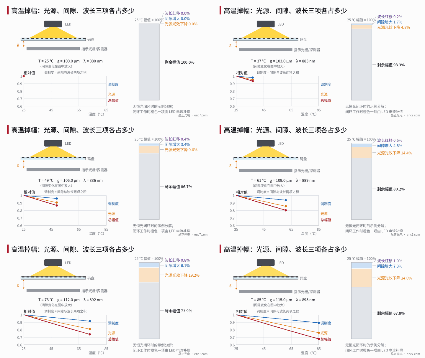
Amplitude loss at high temperature is usually the product of three factors: falling light-source efficiency, a gap change caused by the different thermal expansion of housing and shaft, and a wavelength red-shift that changes near-field conditions. In the example, a 60 K rise gives about −24%, −9.6% and −1.0% respectively, about −32% in total. This article gives the multiplicative model, operating-point sensitivity, and test steps to separate the disc, mechanical and readhead sides starting from the symptom.
An encoder at the back of a motor gives 1 Vpp at room temperature, but after warming to about 85 °C only about 0.7 Vpp remains and the drive starts reporting a weak signal; after stopping and cooling it recovers. Such problems often have more than one source: LED efficiency falls with temperature, the housing and shaft expand differently and change the read gap, and the LED wavelength red-shifts and changes near-field imaging conditions. The mechanisms of the readhead’s internal drift terms are discussed one by one in the library article on readhead temperature; this article starts from the symptom and answers a more practical question: of the lost amplitude, how much belongs to the disc, the mechanics and the readhead, and how a few comparison tests can separate them.
Multiplicative model: three factors
For imaging near-field reading, signal amplitude can be written
A(T)/A(T₀) = [P(T)/P₀] · [m(g(T), λ(T)) / m(g₀, λ₀)]
where P is LED radiant power, m the fundamental modulation, g the read gap and λ the peak wavelength. For a 50% duty-cycle disc under partially coherent illumination (derivation in the library article on the Talbot effect):
m(g, λ) = cos(πλg/p²) · sinc(g·Δα/p)
p is the pitch and Δα the angular width of illumination in the measuring direction. Detector responsivity rises slightly with temperature in the near infrared and offsets a small part; the example below ignores it. The three factors are:
- Light-source efficiency: near-infrared LED radiant power temperature coefficients are commonly about −0.1 to −0.6 %/K, depending on material and current.
- Gap: the readhead is mounted on the housing and the disc on the shaft; the two thermal expansion paths start from the same axial locating face, Δg ≈ α_housing·L_housing·ΔT_housing − α_shaft·L_shaft·ΔT_shaft. An aluminium housing (about 23×10⁻⁶/K) with a steel shaft (assumed about 12×10⁻⁶/K) and about 25 mm axial length gives about 16 μm for a uniform 60 K rise. The sign depends on the structure: when rotor heating makes the shaft hotter than the housing, the difference may shrink or even reverse.
- Wavelength: peak wavelength red-shifts about 0.2–0.3 nm/K. In the cos term λ and g appear as a product, so a wavelength change Δλ is equivalent to a gap change of g·Δλ/λ.
Numerical example: 60 K rise
Assume p = 20 μm, λ₀ = 880 nm, Δα = 20 mrad, g₀ = 100 μm and a 60 K rise:
| Item | Assumption | Amplitude factor |
|---|---|---|
| Light-source efficiency | −0.4 %/K | 0.760 |
| Gap | +15 μm | 0.904 |
| Wavelength | +15 nm (0.25 nm/K) | 0.990 |
| Total | Product of the three | 0.678 |
Total amplitude falls about 32%, about three-quarters of it from the light source. The wavelength term is equivalent to only about 1.7 μm of gap change, an order of magnitude smaller than the mechanical gap term.
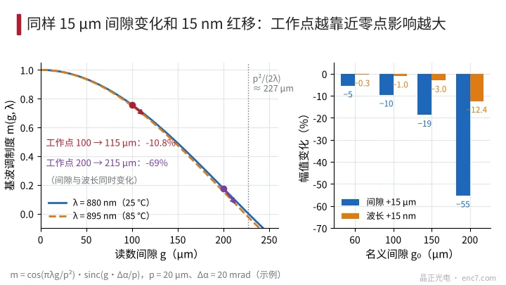
But these proportions depend strongly on the operating point (Figure 2). For the same +15 μm and +15 nm, at a nominal gap of 60 μm the amplitude falls only about 5% and 0.3% respectively; at a nominal gap of 200 μm, close to the fundamental’s zero at p²/(2λ) ≈ 227 μm, they fall about 55% and 12%, about 69% combined. In other words, “severe amplitude loss at high temperature” sometimes is not poor thermal design but an operating point already chosen on the steep part of the curve at room temperature.
When the readhead has a constant-light loop, the light-source term is compensated by LED current and the externally visible loss is only the modulation part, about 11% in the example; the price is about 1/0.76 − 1 ≈ 32% more drive current. If drive headroom is insufficient, the loop saturates at some temperature and amplitude then falls suddenly faster beyond that point — another typical symptom.
Separation tests: look at A and S first, then confirm each term
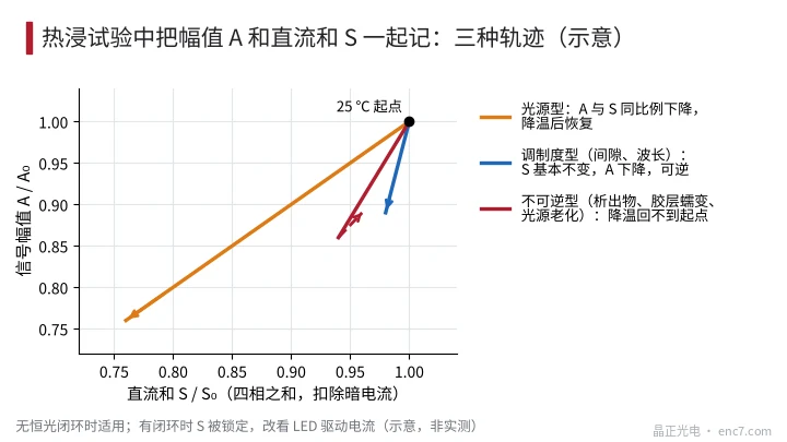
- Record amplitude A and the DC sum S together. S is the sum of the four phase photocurrents, minus dark current measured with the LED off (dark current raises S at high temperature). Heat, soak, then return to room temperature, and plot the trajectory on the A/A₀–S/S₀ plane (Figure 3): A and S falling in proportion means light source or optical-path transmittance; S essentially unchanged while A falls means modulation, i.e. gap, wavelength or disc attitude; not returning to the starting point after cooling means an irreversible factor. With a constant-light loop S is locked, so record LED drive current instead.
- Drive the LED externally at constant current. Disconnect the on-board driver, light the LED directly from a lab constant-current source at the room-temperature current, and measure S versus temperature. This reflects the LED’s own efficiency drift; if it falls more with the on-board driver, the drive current itself is drifting — check the sense resistor and reference.
- Measure gap cold and hot. At room temperature measure the slope of the amplitude–gap curve using shims, then measure the actual gap cold and hot (feeler gauge, capacitive probe, or the relative position of readhead mounting face and disc face); multiply Δg by the slope to predict the modulation change and reconcile with step 1.
- Zoned heating. Heat only the readhead with the mechanics at room temperature to get the light-source, wavelength and circuit terms; heat only the shaft system and housing while blowing air on the readhead to hold it at room temperature to get the gap term. The two together should approximate the whole-unit result.
- Swap wavelength. At room temperature swap in an LED with a different peak wavelength, or measure at two gaps, to find ∂m/∂λ directly; multiply by the actual red-shift to get the wavelength term. With the operating point far from the zero it is usually around 1% and can be ruled out first.
Disc-side causes mostly fall into the “irreversible” category: adhesive or grease outgassing at high temperature and condensing on the disc or window as a thin haze; or the adhesive layer softening so the disc tilts, axial runout increases and the once-per-revolution amplitude variation grows markedly with temperature. Inspect the disc surface under a microscope after cooling and remeasure runout hot to confirm. The optical density of the chrome film itself changes very little with temperature and wavelength and is generally not the main cause.
Engineering notes
- Use the A/A₀–S/S₀ trajectory to classify first: diagonal is light source, vertical drop is modulation, failure to return is irreversible contamination or creep.
- Keep the nominal gap well away from p²/(2λ): at p = 20 μm, moving g₀ from 100 μm to 200 μm increases the effect of the same 15 μm thermal gap change from about 10% to about 55%.
- Wavelength red-shift is equivalent to a gap change of g·Δλ/λ and, with a sensible operating point, is usually the smallest term.
- Constant-light loop drive headroom must cover efficiency loss at maximum temperature plus ageing — at least +32% current in the example.
- In thermal design, keep the axial datums of readhead and disc as close as possible to the same locating face, and check the case where the shaft is hotter than the housing.
- Do the two low-cost tests first — external constant-current drive and cold/hot gap measurement — before deciding whether to change the readhead, the structure or the operating point.
Summary
High-temperature amplitude loss can be decomposed into the product of three factors: light-source efficiency, thermal-expansion gap and wavelength near-field effects — about −24%, −9.6% and −1.0% in the example, though the proportions change sharply with nominal gap. Recording the heating and cooling trajectory of amplitude and DC sum first separates light-source, modulation and irreversible types; external constant-current drive, cold/hot gap measurement, zoned heating and wavelength swap then confirm each term, assigning responsibility to the specific disc, mechanical or readhead side.
Translated from the ENC7 Chinese technical library (article 0224). Read the Chinese original. Need a disc built to your drawing? Request a quote or see our custom encoder discs.
© Langfang Jingzheng Optoelectronic Technology Co., Ltd. All rights reserved. This article was created with AI assistance.