Troubleshooting
Troubleshooting: Signal Amplitude Rises and Falls Once per Revolution — Axial Runout vs Eccentricity

When the amplitude envelope rises and falls once per revolution, it mostly comes from axial runout: the gap slides back and forth on the amplitude–gap curve, and the ripple is approximately the curve’s relative slope times half the runout. Eccentricity only shows up when the track-width margin is insufficient, and the envelope then shows a one-sided dip. This article gives quantitative estimates of both mechanisms, a ripple criterion and steps to separate them.
With the oscilloscope triggered on Z and the disc turning slowly at constant speed, the envelopes of the A and B sines rise and fall slowly together, exactly once per revolution; the Lissajous circle swells and shrinks with it but stays a circle. There are only two once-per-revolution mechanical quantities: tilt of the disc face relative to the rotation axis (axial runout) and offset of the line centre from the rotation axis (eccentricity). Both make the amplitude vary once per revolution, but their mechanisms, magnitudes and remedies differ. This article answers three questions: how much variation each can cause, how much counts as abnormal, and how to tell them apart.
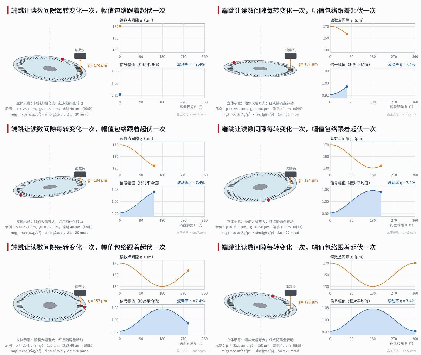
Symptom and criterion
First quantify the phenomenon. Using Z as reference, take the peak-to-peak of A and B cycle by cycle at low speed to get the envelope A(θ), and define the amplitude ripple:
η = (A_max − A_min) / (A_max + A_min)
Three points when recording: A and B must vary together (only one channel changing is an amplitude-mismatch problem, covered separately); the variation must remain after synchronous averaging over several revolutions, showing it is locked to angle; and it must be strictly once per revolution, not twice or n times.
When A and B scale by the same ratio, atan2 interpolation itself produces no error; the harm of amplitude variation is indirect: at minimum amplitude the relative size of fixed offsets grows, the signal approaches alarm thresholds and comparator hysteresis, and sidebands appear at N±1 in the error spectrum. The criteria below are examples and should be adjusted to the product’s alarm threshold and offset budget:
| η | Judgement |
|---|---|
| ≤ 3% | Generally normal assembly level |
| 3%–10% | Check runout and nominal gap; confirm A_min still has margin |
| > 10%, or A_min below 1.3× the alarm threshold | Must be fixed |
Mechanism 1: runout slides the gap along the curve
Axial runout (peak-to-peak T) makes the gap at the read point vary as g(θ) = g0 + (T/2)·cos(θ − θ_T). For imaging near-field reading, the fundamental modulation depends on gap as (derivation in the library article on the Talbot effect):
m(g) = cos(πλg/p²) · sinc(g·Δα/p)
where λ is the wavelength, p the pitch and Δα the angular width of illumination in the measuring direction. Defining the relative slope at the operating point S = (1/m)·dm/dg, for modest runout:
η ≈ |S| · T / 2
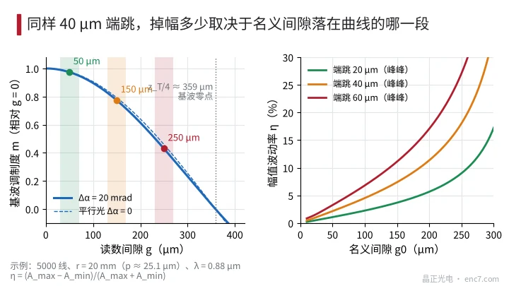
With parallel light S = −(πλ/p²)·tan(πλg0/p²). This shows two things: near zero nominal gap the curve is flat and runout hardly affects amplitude; the closer to the fundamental’s zero at z_T/4 = p²/(2λ), the larger the variation from the same runout.
Example: 5,000 lines, r = 20 mm (p ≈ 25.1 μm), λ = 0.88 μm, assuming Δα = 20 mrad and 40 μm runout:
| Nominal gap g0 | m(g0) | S (%/μm) | η |
|---|---|---|---|
| 50 μm | 0.97 | −0.11 | 2.2% |
| 100 μm | 0.90 | −0.23 | 4.5% |
| 150 μm | 0.77 | −0.37 | 7.4% |
| 200 μm | 0.61 | −0.57 | 11.4% |
| 250 μm | 0.43 | −0.90 | 18.1% |
For 10,000 lines (p ≈ 12.6 μm) at g0 = 25 μm, the same 40 μm runout gives about 17% ripple. Halving the pitch cuts p²/λ to a quarter and the whole curve becomes steeper (Figure 2). Because S < 0, maximum amplitude corresponds to minimum gap — this phase relationship is the basis for discrimination later.
Mechanism 2: eccentricity walks the window radially across the track
When the line centre is offset from the rotation axis by e, the reading window walks radially relative to the track by Δr = e·cos(θ − θ_e). With track radial width W_t, window radial height H and readhead radial mounting offset d0, the one-side margin is:
m_r = (W_t − H)/2 − |d0|
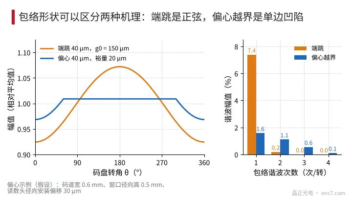
For e ≤ m_r the window stays within the track and amplitude is unaffected; for e > m_r, over the range of angles near the track edge the amplitude drops by (e − m_r)/H, lasting 2·arccos(m_r/e).
Example (assumed): W_t = 0.6 mm, H = 0.5 mm, d0 = 30 μm gives m_r = 20 μm; with 40 μm eccentricity the maximum drop is 4%, lasting 120°, with amplitude unchanged for the other 240°. This envelope is “flat top plus one-sided dip”, with the 2nd harmonic about 70% of the 1st, whereas runout gives an approximately sinusoidal envelope with the 2nd harmonic only about 3% of the 1st (Figure 3).
Eccentricity has two further coupling paths: change of read-point radius mismatches the local pitch with the index grating, giving an amplitude factor sinc(n_w·Δr/r), where n_w is the number of periods in the window; and line direction rotates by ψ ≈ (e/r)·sinθ, giving an amplitude factor sinc(H·ψ/p). With n_w = 40, H = 0.5 mm, e = 50 μm and r = 20 mm, these are only about 1.6% and 0.4%, and both depend on Δr² and ψ², appearing mainly twice per revolution. So once-per-revolution amplitude loss from eccentricity almost always comes from insufficient track margin.
Troubleshooting steps
- Confirm the symptom: trigger on Z, synchronously average several revolutions, confirm once per revolution and A and B in step, compute η and the angle of maximum amplitude.
- Look at envelope shape: do a harmonic decomposition of the envelope; a small 2nd/1st ratio and near-sinusoidal shape points first to runout; flat top plus dip points first to eccentricity overrun.
- Measure runout and compare: measure runout T and its phase at the read radius with a dial indicator or displacement sensor; change the gap by about ±10 μm with shims and measure amplitude at three points to find S; compare |S|·T/2 with the measured η, and check that maximum amplitude faces minimum gap.
- Move the readhead 90° around the circumference and remeasure: both mechanisms rotate with the disc, so envelope phase should shift 90° either way. Compare at both positions: if the envelope extreme always faces the runout extreme, it is runout; if it always faces the radial runout extreme of the disc OD or line ring, it is eccentricity. If runout is unchanged after moving but η changes noticeably, it relates to the readhead’s local radial mounting position — also pointing to overrun.
- Fine-adjust the readhead radially: move it about ±30 μm radially; an overrun-type dip clearly deepens or disappears, while runout-type behaviour is essentially unchanged.
- Remedy: for runout, check hub face perpendicularity, particles on mating faces and adhesive thickness; for eccentricity, check the centring fixture and track-width design.
Engineering notes
- Quantify ripple as η first, then back-calculate runout from η ≈ |S|·T/2 and check whether the two agree.
- The closer the nominal gap to z_T/4, the more sensitive to runout; for 5,000 lines at r = 20 mm, moving g0 from 100 μm to 200 μm increases η for the same runout about 2.5×.
- Runout tolerances for fine-pitch discs must be tightened considerably: halving the pitch makes p²/λ a quarter, and slope at small gaps increases up to about 16×.
- Design the track radial width at least as “window height + 2 × (eccentricity tolerance + readhead radial mounting tolerance)”, or eccentricity will appear as a one-sided dip.
- The envelope harmonic ratio is a quick criterion: a small 2nd/1st ratio points to runout, a large one to overrun.
- Amplitude variation does not itself directly cause interpolation error, but it magnifies the effect of fixed offsets and compresses alarm margin; check margin at A_min separately.
Summary
For once-per-revolution amplitude variation, the runout type is the gap sliding along the amplitude–gap curve, with size set by curve slope and runout together; the eccentricity type only appears when track margin is insufficient, and the envelope is a one-sided dip. Envelope shape, measured runout conversion, readhead repositioning and radial fine-adjustment separate the two, which are then solved through face perpendicularity, centring and track width respectively.
Translated from the ENC7 Chinese technical library (article 0201). Read the Chinese original. Need a disc built to your drawing? Request a quote or see our custom encoder discs.
© Langfang Jingzheng Optoelectronic Technology Co., Ltd. All rights reserved. This article was created with AI assistance.