Troubleshooting
Troubleshooting: Signal Turns Triangular and Amplitude Is Low — Excessive Gap and Window Convolution

A 50% disc convolved with a 50% detection window of the same pitch gives a triangle wave: harmonics fall as 1/n², the third is about 11%, and direct atan2 gives an interpolation error of about ±4.1° electrical. This article derives how the two kinds of blur — penumbra and diffraction — affect the triangle wave and the amplitude, gives tests to tell them apart, and criteria for changing the window duty cycle or adjusting the gap.
On the oscilloscope the A channel is not a sine but a triangle wave with pointed peaks, and the amplitude is also twenty to thirty percent below nominal. Many people’s first reaction is that the two observations contradict each other: a triangle wave needs a small gap, a low amplitude needs a large gap. In fact the triangle wave comes from the geometric convolution of the disc with the detection window, while the amplitude loss comes from blur caused by the gap, and both can occur at the same time; with a fine-pitch disc and an excessive gap, the third harmonic can even grow back because of near-field self-imaging. This article first derives where the triangle wave comes from, then analyses the two kinds of blur — penumbra and diffraction — and finally gives ways to distinguish them and criteria for improvement.
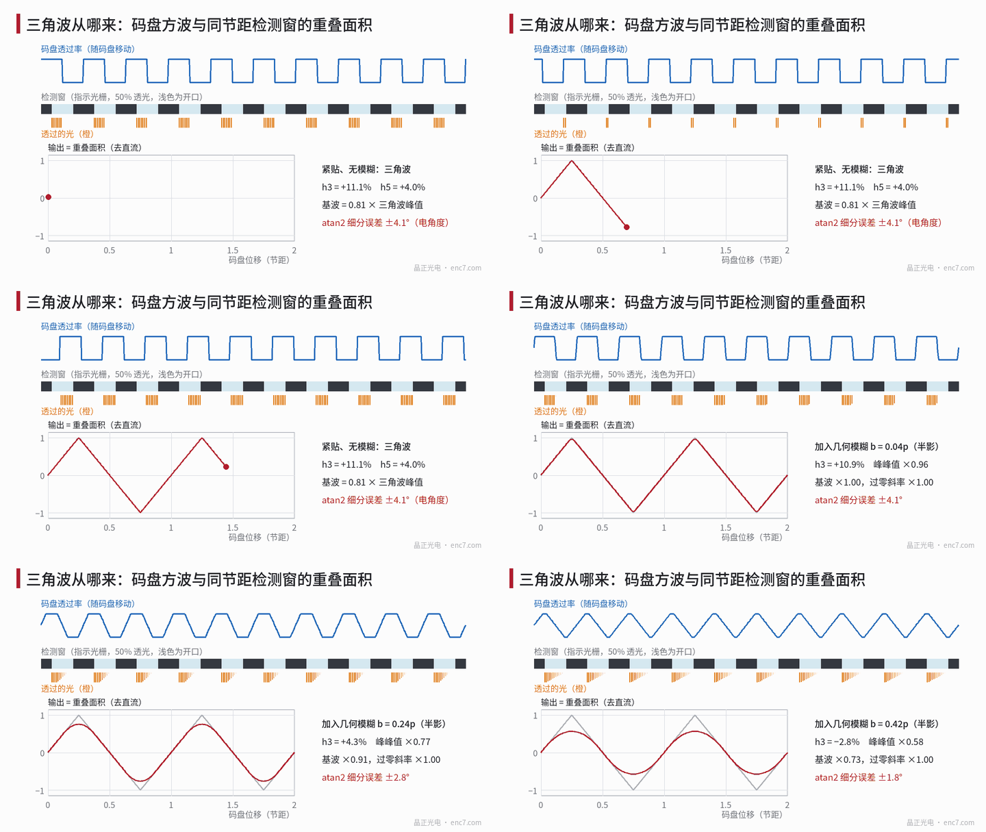
Where the triangle wave comes from: convolution of square wave and detection window
The disc transmittance is a square wave with 50% duty cycle; the detection window (index grating or detector element) has an opening of width w·p. The light received by the detector is the overlap area of the two, which as a function of displacement is their convolution. For w = 0.5 the overlap area rises and falls linearly between zero and half the window area, giving a triangle wave. Its Fourier coefficients are the product of two sinc functions:
c_n ∝ sinc(n/2) · sinc(n·w)
For w = 0.5 the odd harmonics relative to the fundamental are h_n = 1/n², all positive: h3 = 11.1%, h5 = 4.0%, h7 = 2.0%. Solved directly with atan2, the peak interpolation error is about 0.071 rad, i.e. ±4.1° electrical, or about 7.2″ at 2048 lines (for the general relation between harmonics and error see the “squircle” article in this series).
Another number that is easily confused: the fundamental of a triangle wave is only 8/π² ≈ 0.81 of the triangle’s peak value. For a triangle wave measured at 1 Vpp on the oscilloscope, the sine component “seen” by the interpolator is only about 0.81 Vpp, so an amplitude defined by Lissajous radius or by the fundamental naturally reads low.
Low amplitude: two kinds of blur caused by the gap
Geometric blur (penumbra). With an emitting area of width s at distance L from the disc, the blur width of the shadow at gap g is b = s·g/L = g·Δα, where Δα is the angular width of the illumination in the measuring direction. A rectangular blur kernel multiplies the n-th harmonic by sinc(n·b/p). For b < p/2, after convolution with it the triangle wave is still straight near the zero crossings and the zero-crossing slope is unchanged; only the peaks are smeared into parabolas, the peak-to-peak value falls to 1 − b/p and the fundamental to sinc(b/p) (see Figure 1). At b = p/3, sinc(3b/p) = 0: the third harmonic vanishes exactly while about 83% of the fundamental remains.
Diffraction. For a 50% disc the n-th harmonic is multiplied by cos(n²πλg/p²). The fundamental falls slowly as cos(πλg/p²), while the third harmonic changes 9 times faster: it crosses zero and changes sign at p²/(18λ) and is fully restored at 2p²/(9λ). By then the fundamental has dropped to cos(40°) ≈ 0.77. In other words, with a fine-pitch disc and too large a gap the waveform becomes a triangle again while the amplitude has already dropped noticeably — exactly the symptom in the title.
Example (assumed p = 20 μm, λ = 0.88 μm, spectral width 40 nm, illumination angular width 20 mrad):
| Gap g | Fundamental (contact = 1) | h3 | Interpolation error |
|---|---|---|---|
| 0 | 1.00 | +11.1% | 4.1° |
| 25 μm | 0.98 | +0.2% | 1.4° |
| 50 μm | 0.94 | −11.4% | 4.8° |
| 75 μm | 0.86 | −0.6% | 2.7° |
| 100 μm | 0.76 | +12.5% | 7.3° |
At g = 100 μm (about 2p²/(9λ)) the third harmonic is even larger than at contact, the error is about 7.3°, yet only about 76% of the amplitude remains. If the illumination angular width is increased to 50 mrad, at the same gap h3 drops to about 4.8%, the error to about 2.7° and the fundamental to about 0.69; the waveform becomes a “round-topped triangle” (see Figure 2).
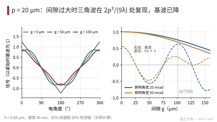
With a coarse pitch the situation is the opposite. For p = 50 μm and an illumination angular width of 50 mrad, the diffraction factor stays above 0.9 over several hundred micrometres and the blur comes mainly from penumbra: at g ≈ 333 μm, b ≈ p/3, the third harmonic vanishes, the error is about 0.5° and the fundamental about 0.77. With a coarse pitch the triangle wave usually appears only at small gaps and rounds off monotonically as the gap increases.
Distinguishing excessive gap from source penumbra
- Fine gap scan, watch h3. Change the gap in steps of about p²/(36λ) (about 13 μm for p = 20 μm) and take an FFT at each step: if h3 alternates in sign with a period of about 2p²/(9λ), it is diffraction; if it decreases monotonically and crosses zero near g·Δα ≈ p/3, it is penumbra.
- Change the wavelength. Fit a red LED (everything else unchanged): diffraction features move with λ, penumbra does not.
- Change the source size. Put a narrow slit aperture in front of the LED, or move the LED back: penumbra decreases accordingly, diffraction is unaffected.
- Look at waveform details. Peak-to-peak drops but the zero-crossing slope is unchanged and the peaks become arcs: penumbra type. The zero-crossing slope also changes with gap, and flat tops alternate with pointed peaks: diffraction type.
- Look at the zero of the amplitude–gap curve. The first zero from diffraction is at p²/(2λ) (about 227 μm for p = 20 μm), that from penumbra at p/Δα (about 1 mm at 20 mrad).
Improvement criteria: change the window or adjust the gap
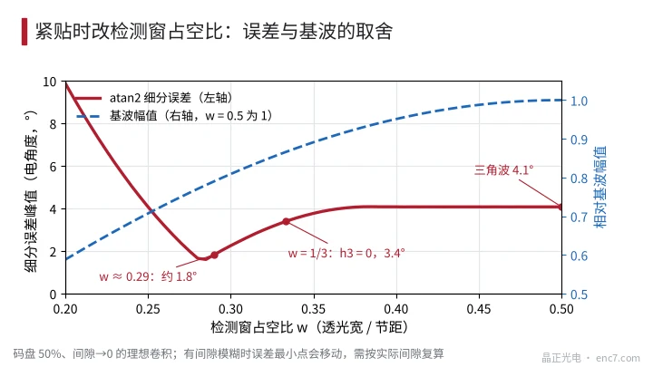
- Enough amplitude, large error (triangle wave at small gap): change the detection window duty cycle. At contact, w = 1/3 cancels the third harmonic, but the fifth is still about −4% and the error about 3.4°; w ≈ 0.29 gives the minimum error, about 1.8°. The price is that the fundamental falls as sin(πw): about 13% less at w = 1/3 (see Figure 3). With gap blur present, the duty cycle of minimum error shifts and must be recalculated for the actual gap; a more thorough approach is multi-window spatial filtering or linearising the triangle wave in the algorithm (see the related article).
- Low amplitude and a triangular waveform (fine pitch, excessive gap): bring the gap back into the range where the fundamental factor is ≥ 0.9, i.e. g ≤ about 0.14·p²/λ (about 64 μm for p = 20 μm), and stay away from the third-harmonic recurrence zone around 2p²/(9λ).
- Coarse pitch, extended source: the working gap can deliberately be placed near g·Δα ≈ p/3, using the penumbra as a low-pass filter and trading about 17% of the fundamental for a nearly sinusoidal waveform.
Engineering notes
- A 50% disc with a 50% detection window gives a triangle wave at contact: h_n = 1/n², error about ±4.1° electrical.
- The fundamental of a triangle wave is only 0.81 of its peak; evaluating amplitude by peak-to-peak or by Lissajous radius differs by about 19%.
- Penumbra-type blur keeps the zero-crossing slope, peak-to-peak drops as 1 − b/p; at b = p/3 the third harmonic is zero.
- With a fine pitch the third harmonic recurs at 2p²/(9λ), where only about 0.77 of the fundamental remains; “triangle wave + low amplitude” is the signature of an excessive gap.
- Three tests — fine gap scan, wavelength change and an added aperture — separate diffraction from penumbra.
- For an error problem, change the detection window duty cycle or use spatial filtering first; for an amplitude problem, bring the gap back first; check both together with the same model.
Summary
The triangle wave is the direct result of convolving the disc square wave with a detection window of the same pitch; the low amplitude comes from penumbra and diffraction caused by the gap. With a coarse pitch the blur is mainly penumbra and the triangle wave rounds off monotonically with gap; with a fine pitch diffraction makes the third harmonic recur at 2p²/(9λ), producing the “triangle wave and low amplitude” symptom. First separate the sources with a fine gap scan, a wavelength change and a change of source size, then decide whether to change the detection window duty cycle or adjust the gap.
Translated from the ENC7 Chinese technical library (article 0229). Read the Chinese original. Need a disc built to your drawing? Request a quote or see our custom encoder discs.
© Langfang Jingzheng Optoelectronic Technology Co., Ltd. All rights reserved. This article was created with AI assistance.