Troubleshooting
Troubleshooting: Steps or Intermediate Levels on the Square Wave — Shorted Channels and Driver Contention
A step on the square wave is usually two outputs shorted together or two push-pull drivers fighting each other; the intermediate level is set by the output-resistance divider: V_mid ≈ V_H·R_L/(R_H + R_L). This article derives the relation between step level and output impedance, explains why the step appears where the other channel switches, and gives a channel-by-channel measurement procedure and criteria for ruling out the disc.
On the oscilloscope the encoder’s channel A square wave has a high level that is not a flat line: the first half is only 2–4 V and only the second half reaches 5 V; the low level is lifted a little as well. The step appears in every period at a fixed position. Some suspect a dirty disc or a faulty readhead, but a disc cannot possibly put an intermediate level on a digital output. Such steps are almost always electrical: two outputs shorted together, or two drivers connected to the same wire. This article calculates the step level from the output-resistance divider, explains why it appears exactly when the other channel switches, and then gives a channel-by-channel troubleshooting procedure.
Model: output-resistance divider
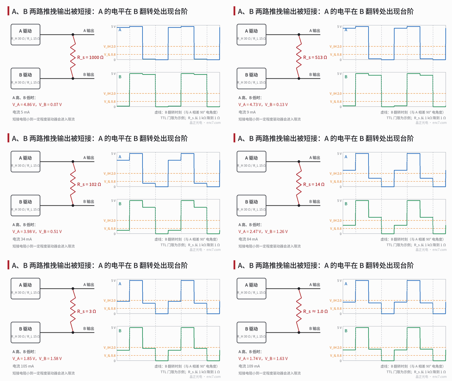
A push-pull output stage can be represented by a Thévenin equivalent: when the output is high it is the supply V_H in series with the on-resistance R_H of the upper transistor; when low it is ground in series with the on-resistance R_L of the lower transistor. Between channels A and B there is a short-circuit resistance R_s (damaged conductor insulation, bridged connector pins, solder bridge).
When both channels are high or both are low, no current flows through R_s and the levels are normal. With A high and B low, current flows from the upper transistor of A through R_s into the lower transistor of B:
V_A = V_H·(R_s + R_L)/(R_H + R_s + R_L), V_B = V_H·R_L/(R_H + R_s + R_L)
As R_s → 0 both tend towards V_mid = V_H·R_L/(R_H + R_L).
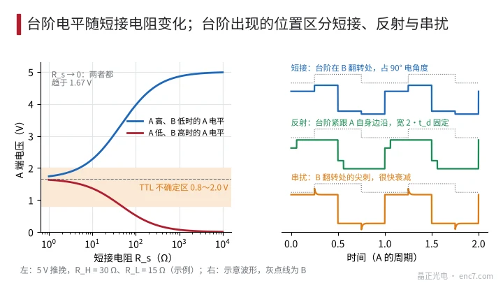
Example (assumed): 5 V push-pull, R_H = 30 Ω, R_L = 15 Ω. With a hard short V_mid ≈ 1.67 V, right in the 0.8–2.0 V undefined region of a TTL input, so the receiver may decide high or low at random; the current is about 111 mA, so most drivers go into current limiting, and the level is then set by the current limit rather than by the resistor divider. With R_s = 100 Ω the high level of A drops from 5 V to 3.97 V and the low level of A rises to 0.52 V; the receiver still reads correctly, but the noise margin is clearly reduced (Figure 2, left).
Two push-pull drivers connected to the same wire (driver contention) is the same circuit with R_s ≈ 0 and each driver switching on its own: when one is high and the other low, the line level falls near V_mid, accompanied by high current and heating.
Why the step is where the other channel switches
A and B are 90° electrical apart, so B switches exactly once within each high half-period of A. The first 90° is “A high, B low”: current flows and the level is pulled down; the next 90° is “A high, B high”: no current, the level recovers. The low half-period behaves the same way. The step boundary is therefore strictly simultaneous with the B edge, and the step width is always 90° electrical, its duration shortening in proportion as speed rises.
The three levels also allow the resistances to be back-calculated. Let V2 be the A level with A high and B low, and V3 the A level with A low and B high; then
(V_H − V2) : (V2 − V3) : V3 = R_H : R_s : R_L
In the example above V2 = 3.97 V and V3 = 0.52 V; the ratio is 1.03 : 3.45 : 0.52, i.e. 30 : 100 : 15. From the waveform alone one can estimate that the short-circuit resistance is a few times the upper-transistor resistance.
A differential RS-422 connection has the same problem, it just shows less readily. Calculated with 120 Ω termination and the driver parameters above, a hard short between A+ and B+ reduces the differential amplitude of A in the half where B is inverted from about 3.6 V to about 1.6 V — still far above the receiver’s ±200 mV threshold, so counting may be completely normal, but the drivers run at high current for long periods and more than half of the noise margin is eaten up.
Distinguishing from reflection and crosstalk
- Short or contention: the step appears where the other channel switches and lasts until the next transition; its width is 90° electrical and varies with speed.
- Cable reflection: the step follows immediately after the channel’s own edge and lasts for the cable round-trip time 2·t_d (about 10 ns per metre of cable length, about 200 ns for 20 m), independent of speed, and changes when matched termination is fitted.
- Crosstalk: a spike where the other channel switches, decaying within a few to a few tens of nanoseconds, with no plateau.
Troubleshooting steps
- Record the three levels and the step position: view A and B on two channels simultaneously, confirm that the step boundary coincides with the B edge, and calculate V2 and V3.
- Disconnect the load: unplug the cable and measure directly at the encoder connector. If the step disappears, the problem is in the cable or the receiver; if it remains, look inside the encoder (damaged output stage, solder bridge on the board).
- Test the cable alone: with power off, measure the resistance between all conductors with a multimeter — the short-circuit resistance can be read directly; flex the cable and re-measure to find crushing and abrasion.
- Test the receiver alone: connect only the receiving equipment, without the encoder, and check whether any input pin outputs a voltage. If it does, that port is configured as an output (e.g. a divided-pulse output port) or another encoder is connected in parallel — driver contention.
- Restore channel by channel: connect one channel at a time to establish which two channels are coupled.
Criterion for ruling out the disc: the disc and readhead optics affect only the analogue signal before the comparator, showing up as duty cycle, phase, amplitude or missing pulses; they cannot create an intermediate level on a digital output synchronous with another channel. As long as the step boundary is strictly simultaneous with the other channel’s edge and the step level does not change with speed, light intensity or gap, there is no need to look further at the disc.
Engineering takeaways
- Estimate an intermediate level on the square wave first with V_mid ≈ V_H·R_L/(R_H + R_L); a hard short with 5 V and 30 Ω/15 Ω gives about 1.67 V, in the TTL undefined region.
- A step boundary simultaneous with the other channel’s edge and a width of 90° electrical is the fingerprint of a short or driver contention.
- (V_H − V2) : (V2 − V3) : V3 = R_H : R_s : R_L estimates the short-circuit resistance directly from the waveform.
- A reflection step follows the channel’s own edge with a fixed width of 2·t_d; crosstalk is a spike, not a plateau — the three can be told apart at a glance.
- With a differential connection a hard short may not lose counts, but the drivers work at high current; it must be fixed, not tolerated.
- The three steps of disconnecting the load, testing the cable alone and testing the receiver alone locate the problem in the encoder, the cable or the receiving equipment.
Summary
A step or intermediate level on the square wave is essentially two outputs fighting through a short-circuit resistance or a direct parallel connection; the level is set by the output-resistance divider and the step falls exactly where the other channel switches, 90° electrical wide. Back-calculate the short-circuit resistance from the three levels, distinguish short, reflection and crosstalk by the step position, then disconnect the load and measure channel by channel — the fault is located quickly, without wasting time on the disc.
Translated from the ENC7 Chinese technical library (article 0238). Read the Chinese original. Need a disc built to your drawing? Request a quote or see our custom encoder discs.
© Langfang Jingzheng Optoelectronic Technology Co., Ltd. All rights reserved. This article was created with AI assistance.