Troubleshooting
Troubleshooting: UVW Commutation Signals Are Not 120° Electrical Apart — Checking the Commutation Track

Commutation errors are multiplied by the number of pole pairs: a mechanical angle Δθ_m corresponds to an electrical angle p·Δθ_m. With 4 pole pairs, e = 10 μm and r = 10 mm, eccentricity contributes only about 0.23°; deviations of several degrees mostly come from threshold and transition zone, sensor position or the motor itself. This article gives a fingerprint reading of the six edge intervals and a troubleshooting procedure against the back-EMF.
A servo motor is noisy during commutation at power-up and the current is high in one sector. On the oscilloscope, the U, V and W square waves are not a clean 120° electrical apart: some edge intervals are 57°, others 63°, and against the motor back-EMF the deviation is even larger. Pattern design, window positions and alignment rules for the commutation track are covered in the UVW commutation track design article of this library; here the question is what to do when the assembled encoder measures wrong — how to tell whether the problem lies in the disc, the readhead, the threshold or the motor itself.
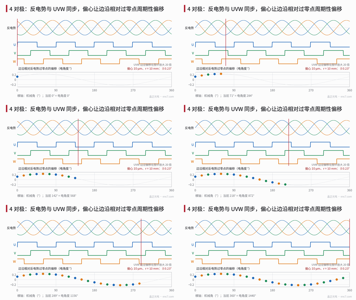
Criteria: six intervals and alignment deviation
For a motor with p pole pairs the electrical angle is θ_e = p·θ_m. The three square waves produce an edge every 60° electrical; in forward rotation the order is U↑, W↓, V↑, U↓, W↑, V↓, giving 6p edges per revolution. Two kinds of quantity are evaluated:
- Interval: the electrical-angle difference between adjacent edges, ideally 60°. It depends only on the encoder and can be measured with the encoder’s own incremental count: 2500 lines with x4 decoding give 10000 counts per revolution; with 4 pole pairs 1 count is about 0.14° electrical, which is ample resolution.
- Alignment: the deviation of each edge from the corresponding back-EMF zero crossing. Its mean value is the calibration error of the commutation offset (calibration method in the commutation angle calibration article of this library); the scatter of individual edges about this mean is the actual “not 120°” problem.
The key point is that mechanical-angle errors are multiplied by the number of pole pairs: the same 0.1 mm tangential error at r = 10 mm is 0.57° mechanical, which becomes 2.3° electrical with 4 pole pairs.
Magnitude of each source
| Source | Conversion | Example | Electrical angle |
|---|---|---|---|
| Commutation track eccentricity | p·e/r | e = 10 μm, r = 10 mm | ±0.23° (once per revolution) |
| Tangential misplacement of the three sensors on a single track | p·Δy/r | Δy = 0.1 mm | 2.3° |
| Light intensity down 20%, fixed threshold | transition width × 0.125 | window 0.3 mm, transition width p·b/r = 6.9° | 0.86° per edge |
| Pattern line-width deviation | p·Δw/r | 5 μm per edge | 0.11° |
| Edges rounded to the line grid | half a line pitch × p | 2500 lines | max. 0.29° |
| Circuit delay | 360°·f_e·Δt | 3000 r/min, 1 μs | 0.07° |
| Motor magnet position error | p·Δs/R | rotor R = 20 mm, 0.1 mm | 1.15° |
The commutation track usually sits on an inner ring with a small radius, so eccentricity has a larger electrical-angle effect there than on the incremental track; yet in the example it is still only 0.23°. Moreover, with a three-track layout the three phases are read at the same angular position, so eccentricity affects all three phases almost equally and the change in adjacent intervals is only about 0.06°. Interval errors of several degrees are therefore usually not eccentricity but threshold and transition zone, sensor position, or an inaccurate back-EMF reference.
The interval pattern is a fingerprint
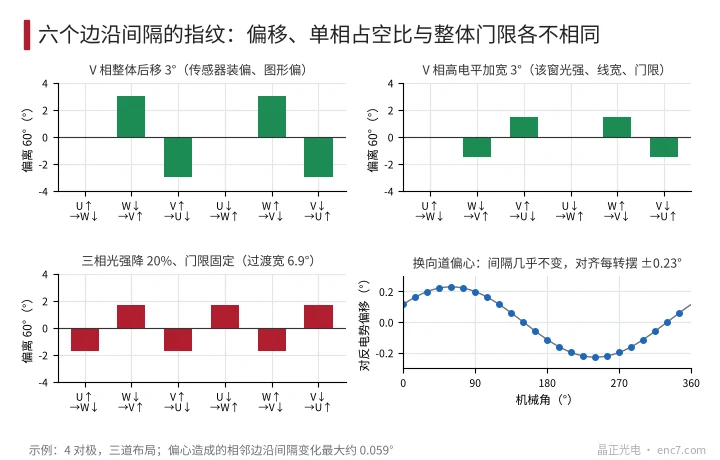
Line up the six interval deviations within one electrical period in order; different sources give different patterns (see Figure 2):
- Whole-phase shift of one phase (sensor of that phase misplaced, pattern of that phase offset): the intervals adjacent to that phase’s edges go one positive, one negative, in the order 0, +δ, −δ, 0, +δ, −δ; the duty cycle of that phase is unchanged.
- Duty-cycle change of one phase (different light intensity in that phase’s window, line-width deviation, threshold offset): the two edges of that phase move in opposite directions; pattern 0, −d/2, +d/2, 0, +d/2, −d/2.
- Threshold problem common to all three phases (overall drop in light intensity, fixed threshold): all rising edges move later and all falling edges earlier; the intervals alternate −, +, and the high level of all three phases narrows at the same time.
- Eccentricity: intervals almost unchanged; the alignment deviation swings once per revolution.
- Comparator hysteresis: all edges shift together in the direction of motion, intervals unchanged; the alignment deviations in forward and reverse rotation differ by about twice the hysteresis angle.
Then check whether the p electrical periods agree with each other: if all p patterns are identical, the problem lies in the readhead, the threshold or the relative position of the three phase patterns; if the pattern varies with the electrical-period index, check the graduation error of the commutation track, eccentricity in a single-track design, or — when comparing with the back-EMF — the motor magnets.
Troubleshooting procedure
- Measure intervals with the encoder only: rotate slowly at constant speed, record the positions of the 6p edges with the incremental count and calculate all intervals, once in forward and once in reverse rotation. This step does not involve the motor.
- Match the fingerprint: use the patterns above to decide between single-phase shift, single-phase duty cycle and three-phase threshold; average the forward and reverse results before deciding, to remove hysteresis.
- Verify the threshold: change the LED current or the read gap and re-measure the duty cycle. If the duty cycle changes clearly with light intensity, the transition zone is wide and the threshold fixed; check against the order of magnitude “20% less light shifts about 0.86°”.
- Compare with the back-EMF: drive the motor externally (windings open), measure the phase back-EMF against an artificial neutral point made of three equal resistors, and record it simultaneously with UVW. From the same set of counts, calculate the intervals between back-EMF zero crossings and the UVW edge intervals: the deviation of the former from 60° belongs to the motor, that of the latter to the encoder, and the mean alignment deviation belongs to the commutation offset calibration.
- Criteria (example; the drive requirements govern): all six intervals within 60° ± 2°, scatter of the individual edge alignment deviations about the mean not exceeding ±2°; the mean itself is handled separately by commutation calibration.
Engineering takeaways
- Work everything out in electrical degrees: a tangential Δs at radius r gives an electrical-angle error p·Δs/r; with 4 pole pairs and r = 10 mm, 0.1 mm is already 2.3°.
- Eccentricity contributes little to commutation — 0.23° in the example — and with a three-track layout it hardly changes the intervals; there is no need to tighten centring specifically for commutation.
- The wider the window transition zone, the more threshold and light-intensity changes affect the edges; make the threshold track the light intensity proportionally, or reduce the tangential width of the window.
- Measure intervals with the encoder’s own count first, then compare with the back-EMF, so that motor magnet errors are not blamed on the disc.
- The sign pattern of the six intervals directly distinguishes single-phase shift, single-phase duty cycle and three-phase threshold problems.
- In a single-track three-sensor design the 120° depends on mounting; during assembly, adjust the sensor positions using the measured intervals.
Summary
When UVW intervals are not 120° electrical, first measure the six edge intervals with the encoder’s own count and use the pattern to decide between single-phase shift, single-phase duty cycle and three-phase threshold problem; eccentricity is only about 0.23° in the example and is rarely the main cause. Then drive the motor and compare with the back-EMF to separate motor magnet errors and commutation offset calibration errors; what remains is the part to fix on the commutation track and readhead.
Translated from the ENC7 Chinese technical library (article 0240). Read the Chinese original. Need a disc built to your drawing? Request a quote or see our custom encoder discs.
© Langfang Jingzheng Optoelectronic Technology Co., Ltd. All rights reserved. This article was created with AI assistance.