Troubleshooting
Troubleshooting: Wide Amplitude Spread After Mounting Discs from One Batch — Variance Decomposition of Disc and Readhead
A wide amplitude spread after mounting discs from one batch is not necessarily the disc’s fault. This article splits the spread into disc, readhead and assembly contributions: near 50% duty cycle the effect is only about 1%, but with DC-sum constant-light control it reaches about 10%; the gap is often larger still. It gives the crossed-experiment and variance-component calculation, the estimation precision and recommended disc consistency specifications.
A batch of discs is mounted in encoders and the signal amplitude ranges from 0.85 Vpp to 1.2 Vpp. The production line’s first reaction is usually “this batch of discs is inconsistent”. But any one amplitude is the joint result of disc, readhead and assembly: the disc’s line width, opacity and cleanliness; the readhead’s light source and gain; the gap and centring at assembly. Without separating the three, swapping discs or swapping readheads may both be wasted effort. This article first estimates the order of magnitude on each side, then gives the crossed disc × readhead experiment and the variance-component calculation, and finally discusses how a disc consistency specification should be set.
How large is each side: an order-of-magnitude estimate first
Amplitude is a product of factors; after taking logarithms the terms add, and so do the variances:
σ²(lnA) = σ²_disc + σ²_head + σ²_interaction + σ²_assembly
Relative standard deviations (CV) are sufficient: for small quantities the standard deviation of ln is approximately equal to the CV.
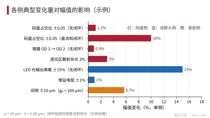
Disc side. Let D be the fraction of the period that is transparent; the fundamental amplitude ∝ sin(πD). At D = 0.5 it is insensitive to D to first order: for D = 0.5 ± δ the amplitude is cos(πδ) ≈ 1 − (πδ)²/2. With a 20 μm pitch, a line-width deviation of ±1 μm means δ = 0.05 and only about a 1.2% drop.
This conclusion, however, depends on how the readhead controls the light. If the readhead runs a constant-light loop on the sum of the four DC phases, the DC sum ∝ D is held fixed and the LED power adjusts as 1/D, so the amplitude becomes ∝ sin(πD)/D, with slope d(lnA)/dD = π·cot(πD) − 1/D = −2 at D = 0.5. The same ±0.05 deviation then changes the amplitude by about ±10%, and wider lines (smaller D) give a larger amplitude. The same batch of discs can show completely different consistency on the two types of readhead.
Other disc-side factors: chrome OD falling from 3 to 2 leaks 1% of the light and lowers the amplitude by about 0.9%; haze or particles in the transparent areas scatter part of the light into a uniform background, reducing the modulation depth roughly in proportion to the scattered fraction.
Readhead side. Without a constant-light loop, the spread of LED light output goes straight into the amplitude, taken as ±15% in the example; a 1% spread in the gain resistor enters as 1%.
Assembly side. The gap is a common large term. In the near-field model the relative slope is S = −(πλ/p²)·tan(πλg₀/p²) (see the axial runout article in this series); for p = 20 μm, λ = 0.88 μm and g₀ = 100 μm it is about −0.57%/μm, so a gap of ±10 μm means ±5.7%.
Crossed experiment: design and calculation
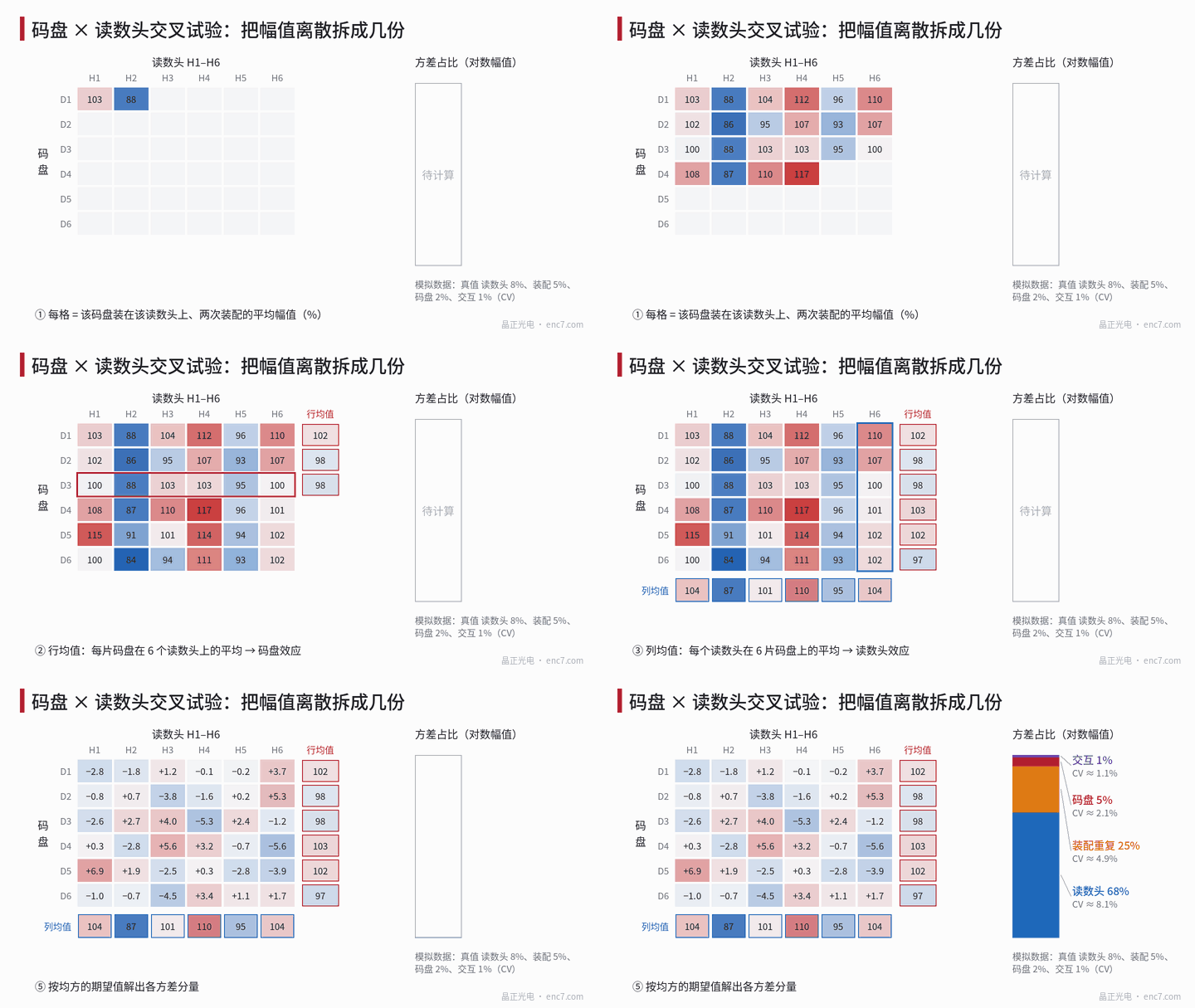
Take a discs and b readheads, fully assemble each combination n times (each time dismounting, remounting and resetting the gap), randomise the order, and measure the amplitude on the same fixture at the same speed and temperature; let y_ijk = lnA. The minimum configuration is 5 × 5 × 2, i.e. 50 assemblies in total.
Let ȳ_i be the mean of each disc, ȳ_j the mean of each readhead, ȳ_ij the mean of each combination and ȳ the grand mean, and compute four mean squares:
- MS_D = b·n·Σ(ȳ_i − ȳ)² / (a − 1)
- MS_H = a·n·Σ(ȳ_j − ȳ)² / (b − 1)
- MS_DH = n·ΣΣ(ȳ_ij − ȳ_i − ȳ_j + ȳ)² / [(a − 1)(b − 1)]
- MS_E = ΣΣΣ(y_ijk − ȳ_ij)² / [a·b·(n − 1)]
Solve for the variance components using the random-effects model:
σ²_assembly = MS_E, σ²_interaction = (MS_DH − MS_E)/n, σ²_disc = (MS_D − MS_DH)/(b·n), σ²_head = (MS_H − MS_DH)/(a·n)
Negative results are set to 0. Meaning of each term: the disc term is the difference between discs themselves (line width, OD, cleanliness); the readhead term is the difference in light source, gain and internal optical path; the interaction term is “a particular disc reads low only on a particular readhead”, for example the combination of track radial position and readhead radial offset; the assembly term is the difference between repeated assemblies of the same combination, mainly gap and centring. If each combination is mounted only once, interaction and assembly cannot be separated.
Worked example (simulated data, assumed true values readhead 8%, assembly 5%, disc 2%, interaction 1%): the 6 × 6 × 2 experiment yields readhead 8.1%, assembly 4.9%, disc 2.1% and interaction 1.1%, with variance shares of about 68%, 25%, 5% and 1% respectively (see Figure 1). The total spread is about 9.8%, of which the disc accounts for only one twentieth; swapping discs will not solve the problem. Tighten the readhead light-source binning or add a constant-light loop first, then control the gap.
Estimation precision: small components need a different method
The crossed experiment is good at answering “which is the big contributor”, but it does not estimate a small disc component reliably. Repeating the simulation under the above assumptions, the disc CV estimated by the 6 × 6 × 2 scheme lies between 0 and 3.1% for the 10%–90% quantiles, with about a 13% probability of being estimated as exactly 0; increasing to 12 discs narrows the interval to about 1.0%–2.7%. The alternative is to fix one reference readhead with a fixed-gap fixture (assumed repeatability 0.6%) and mount each disc 3 times: 6 discs then give an interval of 1.1%–2.7% with only 18 assemblies (see Figure 3).
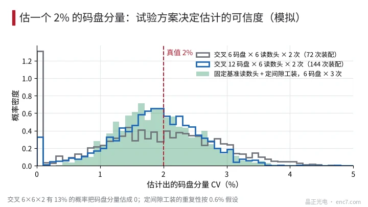
The practical procedure is therefore best done in two steps: first use the crossed experiment to find which side dominates; once it is confirmed that the disc needs controlling, use the reference readhead and fixed-gap fixture for incoming or outgoing inspection of discs.
How to set a disc consistency specification
- Use the relative amplitude on a “reference readhead + fixed gap” as the direct specification, e.g. within ±5% of a master disc (example), stating the measurement conditions (gap, speed, temperature).
- Set the line-width or duty-cycle tolerance according to how the readhead controls the light: without a constant-light loop ±0.05 affects only about 1% and can be relaxed; with DC-sum constant-light control the slope is −2, so keeping the amplitude within ±4% requires the duty cycle to be held to about ±0.02.
- Give lower limits for opacity and cleanliness: with OD not below 3 the effect of light leakage is negligible; give inspectable criteria for particles and haze in the read zone, because scattered background directly lowers the modulation depth.
- Tell the disc supplier about the readhead: the light-control method, window duty cycle and working gap determine how sensitive the result is to disc parameters, and the same specification means different things for different readheads.
Engineering notes
- Take logarithms before decomposing: the variances of each side then add directly and the contribution of each multiplicative factor is clear at a glance.
- Near 50% the duty cycle has a second-order effect on amplitude: ±1 μm (p = 20 μm) gives about 1.2%; but with DC-sum constant-light control it becomes first-order, about ±10%.
- With a relative gap slope of −0.57%/μm (p = 20 μm, g₀ = 100 μm), an assembly tolerance of ±10 μm already exceeds the sum of all disc-side terms.
- In the crossed experiment mount each combination at least twice, otherwise interaction and assembly are confounded; the minimum is 5 × 5 × 2.
- Estimate a small disc component with a reference readhead and fixed-gap fixture; this is far cheaper than enlarging the crossed experiment.
- A disc consistency specification should be based mainly on relative amplitude under clearly stated measurement conditions, with the duty-cycle tolerance then set according to the readhead’s light-control method.
Summary
The amplitude spread after mounting discs from one batch is the combination of three multiplicative factors: disc, readhead and assembly. A crossed disc × readhead × repeated-assembly experiment with variance components gives the share of each side; in the worked example readhead and gap account for more than ninety per cent, the disc only about 5%. The sensitivity on the disc side in turn depends on how the readhead controls the light, so the consistency specification should be set together with the readhead and verified with a reference readhead and fixed-gap fixture.
Translated from the ENC7 Chinese technical library (article 0225). Read the Chinese original. Need a disc built to your drawing? Request a quote or see our custom encoder discs.
© Langfang Jingzheng Optoelectronic Technology Co., Ltd. All rights reserved. This article was created with AI assistance.