Troubleshooting
Troubleshooting: Z Drifts Relative to A/B at High Speed — Unequal Channel Delays

When the Z and A/B paths have unequal delays, Z shifts relative to A/B by 360°·f·Δt electrical degrees — 18° at 500 kHz and 100 ns. This article derives the different effects of delay before and after gating on Z width and position, the permissible values, and a method that measures the Z centre at two speeds and in both directions to separate static offset, hysteresis and delay.
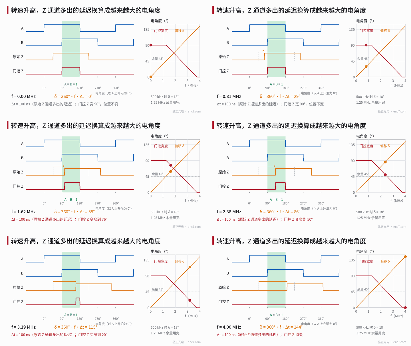
At low homing speed the reference point is rock-steady; raise the homing speed and the reference point starts to shift by one or a few counts. On the oscilloscope, the higher the speed, the further Z moves back relative to the A and B edges, until at some speed Z suddenly narrows or even disappears. Speed-dependent Z width was discussed in another article of this series; there the cause was unequal delay of Z’s own two edges. This article is about the delay difference of Z as a whole relative to A and B: both edges move back together, the width stays the same and the position drifts. It determines up to what speed gated Z holds, and whether the homing position depends on speed.
Model: converting time difference to electrical angle
Let the Z channel have an extra delay Δt relative to the A and B channels and let the A/B output frequency be f. The electrical-angle shift of Z relative to A/B is then
δ = 360°·f·Δt
f = N·n/60, where N is the number of periods per revolution (for interpolated output, count the square-wave periods after interpolation) and n is the speed (r/min). With 2500 lines and 12000 r/min, f = 500 kHz, and Δt = 100 ns corresponds to δ = 18°.
| Δt | 100 kHz | 250 kHz | 500 kHz | 1 MHz |
|---|---|---|---|---|
| 20 ns | 0.7° | 1.8° | 3.6° | 7.2° |
| 100 ns | 3.6° | 9° | 18° | 36° |
| 1 μs | 36° | 90° | 180° | 360° |
δ is proportional to speed, which is the most direct fingerprint of a delay problem; static alignment error and comparator hysteresis do not change with speed.
Is the delay before or after gating?
Before gating (raw-Z filtering, comparator): gated Z is obtained by ANDing raw Z with the A = B = 1 quadrant. If raw Z has width W_r and its centre has a static offset δ0 from the quadrant centre, the gating margin is
m = (W_r − 90°)/2 − |δ0|
For δ ≤ m, gated Z is still a full 90° and its position is locked to the A and B edges — the delay is “absorbed”. For δ > m the gated Z width becomes 90° − (δ − m), and Z disappears for δ ≥ m + 90°. With W_r = 180°, δ0 = 0 and Δt = 100 ns, the margin is used up at 1.25 MHz and Z disappears at 3.75 MHz (see Figure 1).
After gating (output stage, cable, receiver): the gated Z edges coincide with an A or B edge to begin with, so any delay difference after that makes them diverge at the receiver. If the receiver qualifies Z with the A, B state, the effective overlap is only 90° − |δ|; if it latches the count on a Z edge, the latched value changes by one count when δ crosses a count boundary, and the homing position then depends on homing speed (for the details of edge races see the article in this series on the index position in forward and reverse rotation).
Where the delay comes from
| Stage | Mechanism | Magnitude (example) |
|---|---|---|
| Analogue filtering | Z channel RC differs from A/B; delay of a slowly varying signal is about RC | 1 kΩ × 100 pF ≈ 100 ns |
| Comparator | Small index signal amplitude, insufficient overdrive, longer delay | tens of nanoseconds |
| Interpolation circuit | A/B produced by a pipelined interpolator, Z via a separate comparator | implementation-dependent, opposite sign to the two rows above |
| Output and cable | Channel-to-channel skew of the driver, pair length difference (about 5 ns/m) | a few to a dozen or more nanoseconds |
| Receiver | Different optocouplers or digital filter settings per channel | standard optocouplers can reach the microsecond range |
The permissible value is set by the margin and the maximum frequency:
Δt_max = m / (360°·f_max)
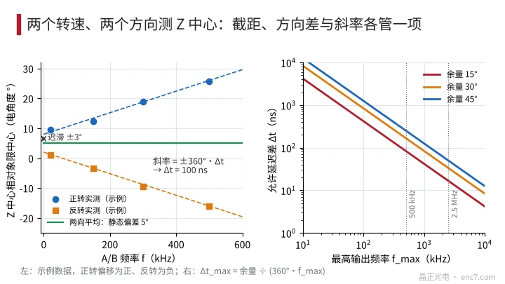
With m = 30°, about 167 ns is permissible at 500 kHz, but only about 33 ns at 2.5 MHz after interpolation (see Figure 2, right). Encoders with interpolated output should therefore generate Z synchronously with A and B in the same digital path, rather than through a separate analogue comparator.
Measurement: two speeds, two directions
- Low-speed reference: with f below one hundredth of the maximum frequency, measure on the oscilloscope the electrical angle of the midpoint of the two Z edges relative to the A rising edge and convert it to the offset φ from the quadrant centre. If a raw-index test point is available, measure raw Z at the same time.
- Repeat at higher speed: take 3–4 frequencies up to near maximum speed and measure once in forward and once in reverse rotation. For reverse rotation convert using the same angular coordinate, i.e. a lag in time corresponds to an opposite shift in angle.
- Separate by fitting: forward φ_F = φ_s + h + 360°·f·Δt, reverse φ_R = φ_s − h − 360°·f·Δt. The mean of both directions is the static offset φ_s; the intercept of their difference at f → 0 is 2h, with h coming from comparator hysteresis; the slope gives Δt.
- Locate by section: measure at the raw-Z test point, at the encoder cable end and at the receiver; the delay difference lies in the section after which the slope appears or increases.
- Criterion: |φ_s| + |h| + 360°·f_max·Δt must not exceed the gating margin, with allowance left for thermal drift and component scatter.
A quick check can also be done on the system side: home once at low speed and once at high speed and compare the two latched positions. If they differ by one or a few counts while repeated low-speed homing is very stable, the cause is almost certainly a channel delay problem.
Engineering notes
- δ = 360°·f·Δt: at 500 kHz, 100 ns is already 18°; after interpolation into the MHz range, even tens of nanoseconds cannot be ignored.
- Gating can only absorb delay that occurs before gating, by an amount of (W_r − 90°)/2 − |δ0|; delay difference after gating turns directly into position offset.
- Design the analogue filtering, comparators and output drivers of Z and of A, B symmetrically; if necessary give the Z channel an adjustable delay.
- With interpolated output, let the interpolation circuit generate Z synchronously, so that A/B do not carry pipeline delay while Z does not.
- Use identical optocouplers and filter settings for all channels at the receiver; delay scatter of standard optocouplers can reach the microsecond range.
- Measuring the Z centre at two speeds and in both directions separates static offset, hysteresis and delay in one go.
Summary
Z drifting relative to A/B at high speed is the delay difference between the two channels converted into electrical angle as 360°·f·Δt. If the delay lies before gating, gated Z first stays unchanged, then narrows once the margin is used up and finally disappears; if it lies after gating, it shows up directly as a speed-dependent homing position. Check Δt_max against the margin and maximum frequency, separate the delay from static offset and hysteresis by measuring at two speeds in both directions, and locate it section by section along the signal chain.
Translated from the ENC7 Chinese technical library (article 0233). Read the Chinese original. Need a disc built to your drawing? Request a quote or see our custom encoder discs.
© Langfang Jingzheng Optoelectronic Technology Co., Ltd. All rights reserved. This article was created with AI assistance.