Troubleshooting
Troubleshooting: Z Signal Amplitude Far Below A/B — Diffraction at the Narrow Reference Slit and Window Mismatch

A low Z signal is first a matter of area: the light through a single slit is about one eighth of that of a 40-period incremental window. Second comes diffraction: with a = 20 μm and g = 0.5 mm, N_F ≈ 0.9 and the window collects only about 70%. This article derives these two terms and window mismatch, and gives criteria for adjusting the gap, multi-slit patterns, widening the window and raising the gain.
On the oscilloscope A and B show 1 Vpp, yet the Z pulse is only a little over a hundred millivolts; swapping several discs changes little, and with a slightly larger gap Z even comes and goes. A low reference signal is often predetermined by design: the index track has only one or a few slits, whereas the detection window of the incremental track contains dozens of periods; in addition, a narrow slit spreads by diffraction across the gap, so the window collects less of its light. This article works out these two terms, then discusses assembly and disc factors such as mismatch between reference window and slit width and radial misalignment, and finally gives the conditions under which each remedy applies. The probability problem of missing or multiple Z pulses is covered in the reference-margin article of this series.
First term: transparent area
The detection window of the incremental track has length L and height h and contains L/p periods. With both the disc and the index grating at 50% duty cycle, the single-phase light flux varies as a triangle wave between 0 and 0.5·L·h·I₀, with fundamental amplitude
A_inc = (8/π²)·0.25·L·h·I₀ ≈ 0.20·L·h·I₀
For a reference single slit of width a and the same height as the window, the geometric peak is Z_peak = a·h·I₀. The ratio of the two is
Z_peak / A_inc ≈ a / (0.20·L)
Worked example: p = 20 μm, a detection window of 40 periods (L = 0.8 mm) and a = 20 μm give a ratio of about 0.12, i.e. the reference signal is only around one eighth of the single-phase incremental amplitude; if the incremental signal is differential (A and A−) while the reference is single-ended, halve it again. This term has nothing to do with disc quality: the readhead must make up the corresponding gain in the reference channel, or a multi-slit pattern must enlarge the transparent area (K slits give about K times; for pattern design see the reference mark pattern article in this library).
Second term: narrow-slit diffraction
Under collimated illumination, the intensity of a slit of width a at distance g is given by the Fresnel integrals
I(x) = ½·{[C(v₂) − C(v₁)]² + [S(v₂) − S(v₁)]²}, v₁,₂ = √(2/(λg))·(∓a/2 − x)
where C and S are the Fresnel integral functions and λ is the wavelength. The shape of the pattern is determined only by the Fresnel number:
N_F = a² / (λg)
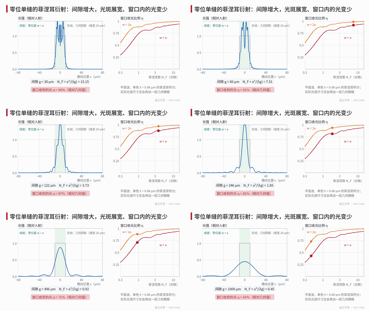
For large N_F it approaches the geometric shadow; when N_F falls to around 1, the slit image is clearly widened and its peak drops. Define η as the ratio of light collected by the reference window to the geometric value. For slit width a = 20 μm and λ = 0.88 μm:
| Gap g | N_F | η (w = a) | η (w = 1.5a) | η (w = 2a) | Reference pulse FWHM (w = a) |
|---|---|---|---|---|---|
| 0.1 mm | 4.5 | 0.88 | 0.95 | 0.97 | 21 μm |
| 0.2 mm | 2.3 | 0.81 | 0.92 | 0.94 | 22 μm |
| 0.5 mm | 0.91 | 0.70 | 0.84 | 0.88 | 24 μm |
| 1.0 mm | 0.45 | 0.43 | 0.60 | 0.73 | 41 μm |
At g = 0.5 mm the window collects only about 70%; if the LED illumination has an angular width of 20 mrad in the measuring direction, a geometric blur of about 10 μm is added and the value drops to about 68%.
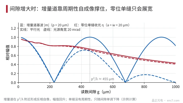
What is easily overlooked: the incremental track is periodic and shows Talbot self-imaging, forming a phase-reversed self-image near p²/λ where the amplitude recovers; a single slit has no periodicity and only widens monotonically with gap (see Figure 3). So “the incremental track has good amplitude at this gap” does not imply that the reference signal is fine; the reference must be checked separately with its own N_F. Combining both terms, in the example above at g = 0.5 mm Z/A is about 0.12 × 0.70 ≈ 0.086.
Third term: mismatch between window and slit
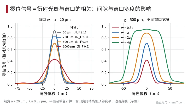
Width mismatch. Geometrically the reference signal is the correlation of two rectangles, i.e. a trapezoid: peak min(a, w)·h·I₀, flat-top width |w − a|, base width a + w. If w is smaller than a, the peak is lost in proportion to w/a: at g = 0.5 mm and w = 0.5a only about 0.41 remains. If w is larger than a, the geometric peak is unchanged and additional light diffracted outside the slit is collected (at w = 2a, η rises from 0.70 to 0.88), at the cost of a wider pulse with a flatter top; the width and edge steepness required by reference gating must be rechecked (see Figure 2, right).
Radial misalignment. If the radial length of the reference slit equals the window height, eccentricity or a radial mounting deviation Δr of the readhead reduces the overlap directly by 1 − |Δr|/h: h = 0.5 mm and Δr = 50 μm mean a 10% loss. One of the two should be longer than the other by 2 × (eccentricity tolerance + mounting tolerance).
Slit-width deviation. Near 50% the incremental line width has a second-order effect on amplitude, but the reference slit width is first-order: a deviation of ±1 μm in a (20 μm slit) shifts the geometric peak by ±5%, and N_F also varies with a². The reference slit width should be given its own tolerance and measured at incoming inspection.
Troubleshooting steps and criteria for remedies
- Calculate the design value first. Compute the expected Z/A from area ratio × η(N_F) and compare it with the measurement. If they agree, the problem lies in the design and individual discs need not be suspected.
- Sweep the gap. Record Z/A over ±50% of the nominal gap. If Z falls faster than A, the operating point is in the low-N_F region.
- Look at the pulse shape. An FWHM clearly larger than the slit width with a low peak indicates diffraction or source blur; a flat, wide top means the window is wider than the slit; narrow and low means the window is too narrow or the slit has been etched too narrow.
- Scan the readhead radially. Move it ±0.1 mm radially and record the plateau width and centre of the reference peak to judge the radial margin.
- Measure the reference slit width on the disc. Measure the actual slit width under a microscope and compare with the drawing.
Choose the remedy according to the conditions:
- Reduce the gap: bring the reference slit to N_F ≥ about 1.5; for a = 20 μm, g ≤ a²/(1.5λ) ≈ 0.3 mm, while checking the amplitude and harmonics of the incremental track at the new gap.
- Widen the slit or change to a multi-slit pattern: make the slit width about equal to the pitch, or use a pattern of K slits; the light increases about K times while the main peak width stays about one slit width.
- Widen the reference window: w of 1.5a–2a recovers about 14–18 percentage points (at g = 0.5 mm), provided the gating allows a wider pulse.
- Raise the reference gain: the most direct, but noise and side lobes are amplified equally; recheck the threshold against the reference margin.
Engineering notes
- The geometric light of a reference single slit is about a/(0.2·L) times the single-phase incremental amplitude – about one eighth for a 40-period window with slit width equal to the pitch – and is a design constant.
- Reference diffraction is governed by N_F = a²/(λg): with a = 20 μm and g = 0.5 mm, N_F ≈ 0.9 and the window collects only about 70%.
- The incremental track has Talbot self-imaging, the reference single slit does not; incremental amplitude cannot be used to infer reference amplitude.
- A window narrower than the slit loses amplitude by w/a; a wider one collects more diffracted light but widens the pulse, so a compromise must be found according to the gating requirements.
- Reference slit-width deviation has a first-order effect on amplitude, ±1 μm gives about ±5%, and should have its own tolerance.
- Remedy priority: first check N_F and gap, then consider multi-slit patterns and window width, and only last raise the gain.
Summary
A Z signal far below A/B is usually the product of two terms, area and diffraction: the transparent area of a single slit is only a fraction of that of the incremental window, and the narrow slit additionally spreads across the gap according to its Fresnel number, so the window collects only part of the light. Adding window/slit width mismatch, radial mismatch and slit-width deviation fully explains the measured value. Calculating the design expectation first, then sweeping the gap and looking at the pulse shape, separates design, assembly and disc problems, and on that basis one can choose between reducing the gap, a multi-slit pattern, a wider window or higher gain.
Translated from the ENC7 Chinese technical library (article 0227). Read the Chinese original. Need a disc built to your drawing? Request a quote or see our custom encoder discs.
© Langfang Jingzheng Optoelectronic Technology Co., Ltd. All rights reserved. This article was created with AI assistance.