Troubleshooting
Troubleshooting: Zero Position Shifts a Few Counts After Swapping to a Same-Type Readhead — Reference Window Position Tolerance

A zero that shifts a few counts after fitting a readhead of the same type comes from mounting location, rotation about the locating pin and internal detection-field tolerance, plus period skips when the reference window exceeds the gating margin. This article converts each term to displacement and counts at the read radius (r = 15 mm, 2500 lines: 1 count ≈ 9.4 μm) and gives an interchangeability budget and a cross-swap test.
A readhead is replaced in service, or a production line re-tests with another readhead of the same type, and the homing position changes: sometimes by one or two counts, sometimes by three or four, occasionally by exactly 4 counts — or Z becomes narrow or appears twice per revolution. Neither disc nor shaft has moved; only the readhead has changed. To answer “how much shift is normal”, the zero position must first be split into its components, each converted into displacement and counts at the read radius; only then can one decide which component to tighten and which to handle by alignment or electronic zero setting. The complete error chain between electrical and mechanical zero is covered in the terminology article of this library; here we look only at the readhead-interchange link.
What determines the zero position
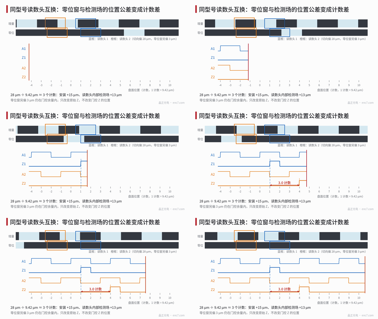
The gated Z is the raw reference signal ANDed with the A = B = 1 quadrant, so its edges are the A and B edges. The position of the zero relative to the disc therefore has two parts:
Z position = s_m + s_i + k·p
- s_m: tangential mounting position of the readhead datum relative to the axis of rotation, set by the locating face, the fit of locating pin and hole, and screw-hole clearance;
- s_i: tangential position of the incremental detection field relative to the readhead datum — an internal readhead tolerance;
- k·p: which signal period the raw Z falls into, set by the position z of the reference window relative to the incremental detection field; p is the pitch.
The first two terms vary continuously and convert directly into counts; the third is a whole-period jump, and k stays unchanged as long as z does not exceed the gating margin.
Conversion basis: at r = 15 mm and 2500 lines, p = 2πr/N ≈ 37.7 μm; with x4 decoding one count is p/4 ≈ 9.42 μm, equal to 129.6″. The zero difference between two assemblies is
ΔC = (Δs_m + Δs_i)/(p/4) + 4·Δk
Interchangeability budget
| Item | Tolerance (example) | Converted |
|---|---|---|
| Readhead location (tangential) | ±15 μm | ±1.6 counts |
| Rotation about locating pin: pin to detection window 10 mm, rotation 1 mrad | ±10 μm | ±1.1 counts |
| Incremental detection field relative to readhead datum | ±10 μm | ±1.1 counts |
| Reference window relative to incremental detection field | ±10 μm (about ±95° electrical) | 0 or ±4 counts |
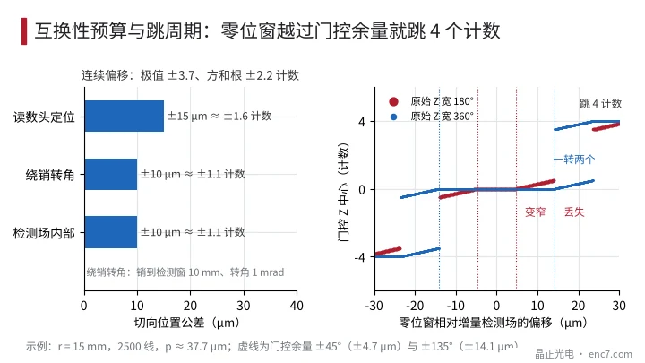
The worst case of the continuous part is ±35 μm, about ±3.7 counts; root-sum-square about ±2.2 counts (Figure 2, left). So “two or three counts of shift after a head swap” is normal scatter with this kind of location. Keeping the zero within ±1 count after interchange requires the sum of the three terms to be squeezed to ±9.4 μm, which is hard to achieve with screws and ordinary locating pins alone.
Angular tolerance is often underestimated: when the readhead is located by one pin and a second screw hole limits rotation, a rotation Δβ produces a tangential displacement L·Δβ at the detection window, where L is the distance from pin to detection window. L = 10 mm and Δβ = 1 mrad give 10 μm, about one count.
Threshold scatter matters less: the edges of the gated Z are set by A and B, so a change in raw-Z threshold only changes the width and centre of the raw Z and uses up gating margin. Only with ungated output does it move the edge directly; a raw Z edge spanning 90° electrical moves about 9° for a 10% threshold change — just 0.1 count.
Period skips: reference window beyond the gating margin
With raw Z width W_r, the gating margin is ±(W_r − 90°)/2:
- W_r = 180°: ±45°, i.e. ±4.7 μm. An internal reference-window tolerance of ±10 μm already exceeds this, so some readheads show a narrowed Z; for offsets between 135° and 225° Z is lost, and beyond that it jumps to the adjacent period — the zero shifts by exactly 4 counts.
- W_r = 360°: ±135°, i.e. ±14.1 μm, which covers a ±10 μm tolerance; beyond it each end of the raw Z cuts into a quadrant and two narrow Z pulses appear per revolution, and further out it again jumps 4 counts (Figure 2, right).
So if the zero difference is an exact multiple of 4, or comes with a narrowed, missing or doubled Z, check the position of the reference window relative to the incremental detection field, not the mounting location. The larger the radius difference between index track and incremental track on the disc, the larger the relative phase shift caused by eccentricity and azimuth, which also consumes this margin (see the reference-mark alignment design article in this library).
Cross-swap test
- Establish a reference: keep one reference readhead on the same disc that is never removed, or couple a reference encoder to the shaft; express the Z position of the readhead under test in counts of the reference.
- Cross combinations: take 2–3 readheads and 2 mounting positions (or 2 machine bodies); mount and remove each combination 3 times and record the Z position.
- Separate sources: if a given readhead shows the same offset on different bodies, the cause is inside the readhead (s_i or z); if the offset follows the body, it is the mounting face and locating holes; large scatter between remounts of the same combination means poor location repeatability.
- Look at the numerical signature: if offsets are continuously distributed, back-calculate the displacement at 9.42 μm/count and compare with mounting and internal tolerances; if offsets cluster at 0 and ±4, check the reference window and gating margin, and if necessary look at the raw Z test point to see its position relative to the A = B = 1 quadrant.
- Decide the remedy: continuous offset — tighter locating pins or signal-based alignment at assembly; period skips — wider raw Z and tighter reference-window tolerance; where the system allows, recalibrate the zero offset in the controller after a readhead replacement.
Engineering takeaways
- Convert first: at a 15 mm read radius and 2500 lines, 1 count ≈ 9.4 μm, so 28 μm tangential is 3 counts.
- Tangential location of the readhead and rotation about the pin are often larger than the internal readhead tolerances; if interchangeable zero is required, tighten location first.
- To keep the zero within ±1 count after interchange, the sum of the three continuous tolerances must be below p/4; with fine-pitch discs this practically means signal-based alignment or electronic zero setting.
- A zero difference that is an exact multiple of 4, or comes with a narrowed, missing or doubled Z, points to the reference-window position relative to the incremental detection field and to the raw Z width.
- With a raw Z about one period wide, the gating margin is ±135° — much wider than ±45° at 180° width — which helps interchangeability.
- A cross-swap test counted against a reference readhead separates three classes of source: readhead internals, mounting face and remount repeatability.
Summary
A zero that shifts a few counts after fitting a same-type readhead has a continuous part from mounting location, rotation about the pin and internal detection-field tolerance, converted to counts via p/4; jumps of exactly 4 counts come from the reference window exceeding the gating margin. Converting every term to micrometres and counts at the read radius for an interchangeability budget, and separating sources with a cross-swap test, shows whether to tighten location, widen the raw Z, or recalibrate the zero after a head swap.
Translated from the ENC7 Chinese technical library (article 0235). Read the Chinese original. Need a disc built to your drawing? Request a quote or see our custom encoder discs.
© Langfang Jingzheng Optoelectronic Technology Co., Ltd. All rights reserved. This article was created with AI assistance.