Custom discs
Vernier Track Combinations: Line Counts and Tolerance Budget
Vernier principle and error margins are covered by separate articles in this library; this one gives the design steps: choose the main-track line count from the absolute resolution, choose an N − 1 or N − 2^k combination, write down the weights of each decision variable, split the ±½ margin among interpolation, eccentricity and noise, and tabulate the allowable interpolation error, noise and eccentricity for six combinations at r = 10–40 mm.
Vernier absolute encoding uses several sine/cosine tracks with slightly different line counts and obtains the absolute position from the beat of their phase differences. The principle and the question of how large a phase error may become before a period is skipped have already been treated (see the two articles on vernier encoding and error margins in this library). When it comes to drawing the disc, the problem turns into concrete design choices: how many lines for the main track, which vernier tracks to pair with it, in what order to arrange the tracks, and how much eccentricity and interpolation error can each be allowed. This article chains these steps together and ends with a table of combinations and tolerances for r = 10–40 mm.
Step one: choose the main-track line count from the absolute resolution
Both the final resolution and the accuracy of a vernier encoder come from the main track: counts per revolution = N × interpolation factor, and the interpolation error of the main track goes straight into the accuracy. The main-track line count N is bracketed by three constraints:
- Resolution: N ≥ 2^B / k_max, where B is the target number of bits and k_max the interpolation factor permitted by the signal-to-noise ratio;
- Pitch: p = 2πr/N must not fall below the lower limit required by the scanning method;
- Vernier decision: the larger N, the harder the decision; see below.
Example: r = 20 mm, target 2²¹ counts (about 0.62″), interpolation factor 1024, main track N = 2048, pitch 61.4 μm.
Step two: choose the combination and write down the decision weights
Let e_i be the phase error of each track (in periods of that track). Each solving stage goes from a beat signal with P_a periods per revolution to a signal with P_b = R·P_a periods per revolution; the deviation of the decision variable is a linear combination of the track errors, ΔD = Σ a_i·e_i, and reliable solving requires |ΔD| < ½. Weights of common combinations:
| Combination | Gain R of each stage | Weights a_i per stage | Max. Σ|a_i| |
|---|---|---|---|
| Two tracks N, N − 1 | N | (N − 1, −N) | 2N − 1 |
| Three tracks N, N − 1, N − S | S, N/S | (S − 1, −S, 1); (N/S − 1, 0, −N/S) | max(2S, 2N/S − 1) |
| Four tracks N, N − 1, N − S₁, N − S₂ | S₁, S₂/S₁, N/S₂ | written out stage by stage in the same way | approx. 2 × largest stage ratio |
S is chosen as 2^k so that the period ratios of all stages are integers. With three tracks, S ≈ √N is the most balanced choice: for N = 1024 take S = 32, so both stages have a gain of 32; for N = 2048, S = 32 or 64 with a largest stage ratio of 64; four tracks can keep each stage within 16. Vernier line counts such as 2016 or 1984 need not be powers of 2 — only their phase is used.
Step three: allocate the ±½ margin
Every stage must satisfy
Σ|a_i|·ε + ΔD_ecc + 6.1·σ·√(Σa_i²) + ΔD_other ≤ ½
where ε is the upper limit of interpolation error per track (in periods, added with worst-case signs), σ the phase noise per track, 6.1σ corresponds to a single-skip probability of about 10⁻⁹, and ΔD_other includes sampling skew, graduation error and thermal drift. Example allocation: interpolation 40%, eccentricity 20%, noise 30%, other 10%.
Eccentricity causes an angular error (e/r_i)·sin(θ + α) on each track, i.e. a phase error e_i = N_i·e/(2π·r_i). The common part cancels in the decision, leaving
ΔD_ecc = (e/2π)·|Σ a_i·N_i / r_i|
This is proportional to the track spacing and inversely proportional to r². Sampling skew belongs to the same category: in the second stage of the three-track 2048/2047/2016 combination, with a 100 ns sampling skew between tracks, the 10% margin is used up above about 230 r/min. Vernier solving should therefore be done at standstill or low speed, or with simultaneous sample-and-hold on all tracks.
Step four: track order
The main track goes on the outermost radius, where the pitch is largest and the angular error from eccentricity smallest. The order of the remaining tracks affects ΔD_ecc: the tracks used by the stage with the larger gain should sit right next to the main track. Take 2048/2047/2016 at r = 20 mm with 0.8 mm track spacing: the second stage has a gain of 64 and uses the 2016 track. With 2016 as the first track inside the main track, the allowable eccentricity is 2.24 μm; with 2047 as the first track it is only about 1.1 μm. All tracks are formed on the same photomask, so concentricity between tracks is guaranteed by the mask; the three pitches are about 61.4, 59.8 and 56.5 μm, and the index gratings of the readhead must be designed for the respective pitch.
Tolerance budget table
Calculated with the above allocation, 0.8 mm track spacing and the track order giving the largest allowable eccentricity (the variation of allowable eccentricity with radius is shown in Figure 2, left):
| Combination | Interpolation error per track ε | Noise per track σ | Allowable eccentricity at r = 10 / 20 / 30 / 40 mm |
|---|---|---|---|
| Two tracks 256/255 | 0.14° | 0.024° | 1.1 / 4.6 / 10.5 / 18.9 μm |
| Three tracks 1024/1023/992 | 1.12° | 0.20° | 1.0 / 4.5 / 10.5 / 19.0 μm |
| Three tracks 2048/2047/2016 | 0.57° | 0.10° | 0.5 / 2.2 / 5.2 / 9.4 μm |
| Four tracks 2048/2047/2040/1920 | 2.25° | 0.40° | 1.1 / 4.7 / 10.9 / 19.6 μm |
| Three tracks 4096/4095/4032 | 0.56° | 0.10° | 0.13 / 0.56 / 1.3 / 2.3 μm |
| Four tracks 4096/4095/4080/3840 | 2.25° | 0.40° | 0.32 / 1.5 / 3.5 / 6.4 μm |
(ε and σ are electrical angles; main-track pitch: 1024 lines at r = 10 mm 61.4 μm, 2048 lines at r = 20 mm 61.4 μm, 4096 lines at r = 40 mm 61.4 μm.)
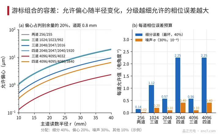
Some conclusions: the two-track 256/255 combination allows about the same eccentricity as the three-track 1024 one, but only 0.14° interpolation error — 8 times stricter. A 1% DC offset causes about 0.57° interpolation error, exactly the whole interpolation budget of the three-track 2048 design; only four tracks leave a reserve. With a 4096-line main track and a three-track combination, the allowable eccentricity at r = 20 mm is only about 0.56 μm, which is hard to achieve in assembly; switch to four tracks or a larger radius.
Engineering checklist
- The main track sets resolution and accuracy, the vernier tracks only consume decision margin: first fix the main-track N from pitch and interpolation factor, then choose the combination.
- Two-track combinations only suit N up to about 256: Σ|a| = 2N − 1, and at N = 256 the interpolation error per track must be below about 0.14° electrical.
- For three tracks choose S as the power of 2 near √N; for N ≥ 2048 consider four tracks, with no stage gain above about 16 and up to about 2.25° interpolation error allowed per track.
- The eccentricity term (e/2π)·|Σ a_i·N_i/r_i| is proportional to track spacing; put the tracks used by the stage with the largest gain right next to the main track — in the example this doubles the allowable eccentricity.
- Do vernier solving at standstill or low speed, or sample all tracks simultaneously: in the three-track 2048 design a 100 ns sampling skew uses up the 10% margin at about 230 r/min.
- The allocation ratios in the table are an example; reallocate them according to measured interpolation-circuit error and noise and to the eccentricity achievable in assembly, and keep at least 10% reserve.
Summary
The design sequence for a vernier disc is: fix the main track from resolution and pitch, choose a two-, three- or four-track combination according to the size of N, write down the decision weights of each stage, split the ±½ margin among interpolation error, eccentricity, noise and sampling skew, and then reduce the eccentricity term with track order and track spacing. The larger the main-track line count, the more an additional vernier stage is needed to keep interpolation error and assembly eccentricity within achievable limits.
Translated from the ENC7 Chinese technical library (article 0305). Read the Chinese original. Need a disc built to your drawing? Request a quote or see our custom encoder discs.
© Langfang Jingzheng Optoelectronic Technology Co., Ltd. All rights reserved. This article was created with AI assistance.