Encoder-disc terminology
Warp, Bow and Flatness: Definitions and Conversion of Three Terms

Flatness is the separation of two parallel planes that enclose a single surface; warp is the difference between the maximum and minimum of the median surface relative to a reference plane; bow is the signed departure of the median-surface centre from a three-point reference plane. This article evaluates all three on bowl, saddle and trefoil-ripple forms, explains the difference between free-state and chucked measurement and self-weight deflection, and gives marking recommendations for encoder-disc drawings.
An encoder-disc drawing writes “flatness ≤ 0.01 mm”, the glass supplier’s inspection sheet writes “warp ≤ 10 μm”, and an incoming-inspection report then shows “bow −8 μm”. In Chinese the three words are often lumped together as “warp”, but they refer to different surfaces, are calculated differently and are measured in different states. On one and the same disc the three numbers can be 10, 10 and 0; more important, none of the three directly answers the question the encoder cares about: how much the gap at the reading circle rises and falls in one revolution.
Definitions of the three terms
Flatness. In the geometric-tolerance sense (GB/T 1182, ISO 1101) the actual surface to be measured shall lie between two parallel planes a distance t apart, and the value is assessed by the minimum-zone method: the pair of planes for which that separation is smallest. It applies to one surface, the film side or the back, so thickness variation enters the result directly. A “flatness” computed from a least-squares plane or a three-point plane as reference is usually larger.
warp. The definition used in the wafer industry (the SEMI system of standards, descending from the former ASTM F657 and F1390): in the free, unclamped state, the difference between the maximum and the minimum of the distance from the median surface (the locus of mid-points between the front and back surfaces) to a reference plane; always positive. Depending on the edition of the standard, the reference plane is a least-squares plane or a three-point plane. Because the median surface is used, thickness variation (TTV) is excluded.
bow. The definition in the same system (descending from the former ASTM F534): the departure of the centre point of the median surface, in the free state, from a reference plane set by three equally spaced points on a circle at a stated distance from the edge. It is signed, so convex and concave can be distinguished, but it looks only at that single centre point.
The glass industry often lays the glass on a surface plate and measures the largest gap with a feeler gauge, or writes the ratio of camber to length as a percentage. That method includes the flattening effect of self-weight and differs from both of the free-state definitions above.
Evaluating the three forms
Let the disc have outer radius R = 20 mm and let the median surface have the shapes (examples):
bowl z = a·r²; saddle z = b·r²·cos2(θ − φ); trefoil ripple z = c·(r/R)³·cos3(θ − φ)
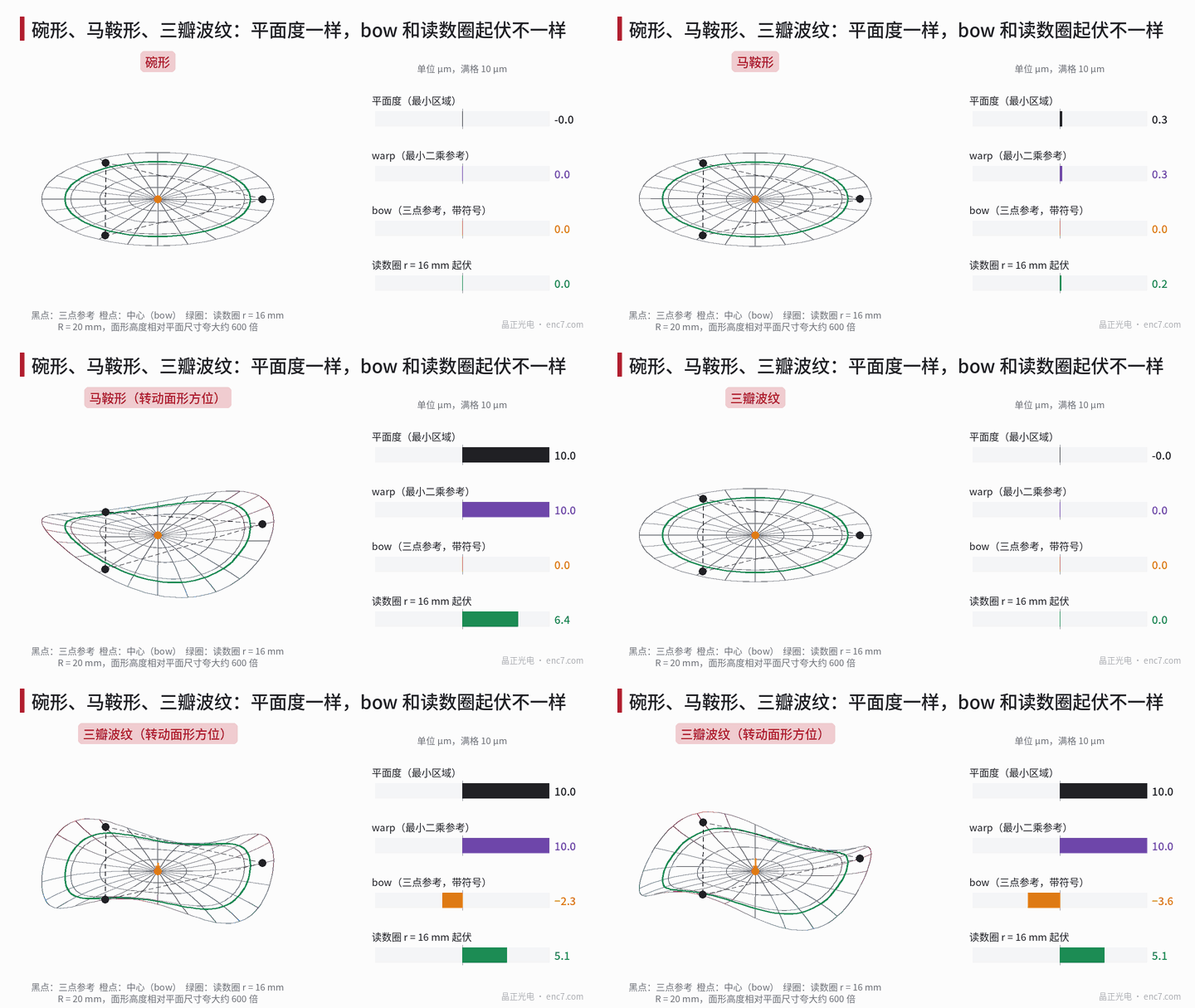
Bowl: the minimum zone is simply two horizontal planes, and flatness = warp = a·R². All three bow reference points lie on R_ref and have the same height, so bow = −a·R_ref² and the ratio of bow to flatness is −(R_ref/R)².
Saddle: flatness = warp = 2b·R². The three reference points are 120° apart, and the values of cos2θ at these three points always sum to zero, so the reference plane passes exactly through the height of the centre and bow is identically 0, whatever the azimuth.
Trefoil ripple: flatness = warp = 2c. The three reference points 120° apart fall on the same phase of cos3θ, the reference plane is horizontal, and bow = −c·(R_ref/R)³·cos3φ, varying with the azimuth of the reference points relative to the ripple between ±c·(R_ref/R)³.
Taking a·R² = 10 μm, b·R² = 5 μm, c = 5 μm, R_ref = 18 mm and a reading circle r = 16 mm, the numerical results are:
| Form | Flatness (minimum zone) | warp | bow | Rise and fall on the reading circle |
|---|---|---|---|---|
| Bowl | 10.0 | 10.0 | −8.1 | 0 (overall lift 6.4) |
| Saddle | 10.0 | 10.0 | 0 | 6.4, 2 times per revolution |
| Trefoil ripple | 10.0 | 10.0 | −3.6 ~ +3.6 | 5.1, 3 times per revolution |
All units are μm. Flatness and warp are identical for the three forms; bow ranges from −8.1 to 0. For an encoder, a bowl changes only the nominal gap; it is the saddle and the trefoil ripple that make the gap rise and fall each revolution (a saddle causes the amplitude to vary twice per revolution; see the article on the signal-problem atlas in this library).
When the form is asymmetric, the choice of reference plane also changes the result. For a tilted bowl such as z = 5·(r/R)³·cosθ + 3·(r/R)² μm, the minimum-zone flatness is 4.3 μm, the maximum-minus-minimum relative to a least-squares plane is 5.4 μm, and relative to a three-point plane 4.8 μm — a difference of about a quarter.
Free state, chucked state and self-weight deflection
Chucked state. A thin disc pulled flat on a vacuum chuck yields a surface shape that is mainly thickness variation plus the flatness of the chuck itself; warp and bow are masked. This state is suitable for assessing gap uniformity in proximity exposure, not for assessing the form after assembly.
Free state. Measured on supports, the result is the intrinsic form plus self-weight deflection. For a solid circular plate simply supported at the periphery, the centre deflection under self-weight is
w = (5 + ν)·q·R⁴ / (64·(1 + ν)·D), q = ρ·g·t, D = E·t³ / (12·(1 − ν²))
where t is thickness, ρ density, E and ν the elastic modulus and Poisson’s ratio, and D the flexural rigidity of the plate. The deflection grows as R⁴/t². Worked values for soda-lime glass (E about 70 GPa, ν = 0.22, ρ = 2.5 g/cm³):
| Outer diameter × thickness | Self-weight deflection |
|---|---|
| Ø40 × 1.0 mm | 0.04 μm |
| Ø100 × 1.0 mm | 1.7 μm |
| Ø80 × 0.5 mm | 2.7 μm |
| Ø80 × 0.3 mm | 7.6 μm |
| Ø100 × 0.3 mm | 18.6 μm |
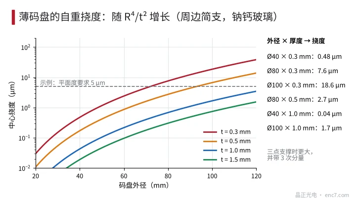
Self-weight can be ignored on a small disc, but not on a large, thin one. It is removed by measuring twice and flipping the part: the intrinsic form reverses sign after the flip, while self-weight deflection keeps its direction, so taking half the difference of the two results, matched by coordinate, cancels self-weight — provided the support layout is symmetric about the flip axis. With three-point support the deflection is larger than for simple peripheral support and carries a third-order component; it must be calculated for the actual supports.
Once mounted on a hub the disc is clamped at the centre and free at the outer edge. The same plate theory gives, for an Ø80 × 0.3 mm disc on a Ø12 mm hub mounted with the shaft vertical, an outer-edge sag under self-weight of about 7.5 μm; this is an axisymmetric component and changes only the nominal gap. With the shaft horizontal, gravity lies in the plane of the disc and this term disappears.
Marking recommendations
- State the term and the assessment method: flatness by the minimum-zone method; if warp or bow is used, state the standard relied on, how the reference plane is taken, and the circle on which the three points lie.
- State the measurement state: free (support arrangement, and whether self-weight has been subtracted) or chucked; the same number has entirely different meanings in the two states.
- State the assessment region: the entire surface, the film side, or the reading annulus. What the encoder actually needs is the gap variation at the read radius after assembly; the peak-to-peak axial runout of the reading circle, or its 2nd- and 3rd-order components, can be specified directly.
- For a thin disc also give TTV: chucked-state flatness mainly reflects thickness variation, free-state warp reflects bending, and the two complement each other.
Engineering points
- The same 10 μm of flatness produces no gap variation in a bowl, but 6.4 μm of twice-per-revolution variation at r = 16 mm in a saddle; using flatness to control form is therefore conservative.
- bow is completely ineffective on a saddle (identically zero) and changes sign with the azimuth of the reference points on a trefoil ripple, so it should not be used alone as a form specification for an encoder disc.
- For discs of outer diameter 80 mm or more and thickness 0.5 mm or less, free-state measurement must subtract self-weight deflection, either by the flip method or by calculation for the actual supports.
- When the form is asymmetric, minimum-zone, least-squares and three-point references can differ by about a quarter; supplier and customer must agree on the assessment method.
- The acceptance quantity that relates directly to the reading gap is the axial runout of the reading circle after assembly, together with its harmonic components; a form specification is only the incoming-inspection premise for that quantity.
Summary
Flatness governs a single surface, warp governs the overall bending of the median surface, and bow looks only at the centre point. The same disc can have both flatness and warp equal to 10 μm and bow equal to zero. Drawings should state the term, the assessment method, the measurement state and the assessment region, and should take the gap variation on the reading circle as the final criterion.
Translated from the ENC7 Chinese technical library (article 0275). Read the Chinese original. Need a disc built to your drawing? Request a quote or see our custom encoder discs.
© Langfang Jingzheng Optoelectronic Technology Co., Ltd. All rights reserved. This article was created with AI assistance.