Encoder disc basics
What Is an Encoder Disc? The Most Essential Part Inside an Encoder

Open up an optical encoder and you find a light source, an encoder disc, a readhead and a circuit board. The disc is the part that turns with the shaft and carries a precision pattern. This article explains where it sits, what it does, why it sets the upper limit of the encoder, and the common forms: discs, code strips and linear scales.
People who open an optical encoder for the first time are often a little surprised: there is no complicated mechanism inside — a shaft, a circuit board, a housing, and between them a thin round plate. That plate is the encoder disc. It looks unremarkable, yet it is the only part of the whole encoder that actually carries a “scale”.
Where the disc sits
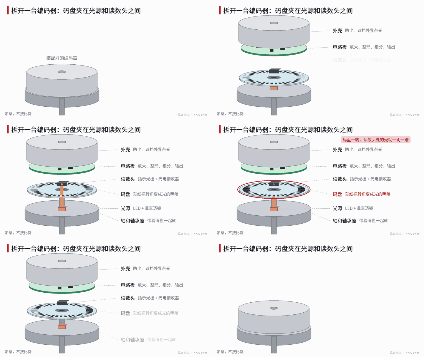
Taking a common transmissive optical encoder as an example, the order from bottom to top is roughly: shaft and bearing housing, light source, encoder disc, readhead, circuit board, housing — see Figure 1.
- The disc is fixed to the shaft by a hub and turns with it;
- the light source is on one side of the disc and the readhead on the other; both are stationary;
- the circuit board processes the signals from the readhead, and the housing keeps out dust and ambient stray light.
A reflective design places the light source and the receiver on the same side of the disc, but the role of the disc is the same.
What the disc does
In one sentence: it turns “how far the shaft has rotated” into “how many times the light has gone bright and dark”.
The disc carries one or more rings of precision pattern. The incremental track has equally spaced lines, the index track has only a single window per revolution, and an absolute disc additionally has coded tracks. The lines block light and the gaps let it through. Each time the disc moves by one pitch, the light at the readhead goes through one bright–dark cycle. The index grating and photodetectors in the readhead turn this variation into an electrical signal, which the circuit then shapes into pulses or passes on for interpolation.
In other words, all the position information in an encoder originally comes from the pattern on the disc. The other parts handle illumination, detection, processing and protection.
Why the disc sets the upper limit
The circuit can amplify, filter and interpolate, but it can only work with the signal the disc provides. Several properties of the disc map directly onto encoder specifications:
| Disc property | Corresponding encoder specification |
|---|---|
| Line count | Native resolution: the angle covered by one signal period |
| Accuracy of line positions | Accuracy: line position errors go straight into the reading |
| Concentricity of tracks and shaft | Eccentricity error: a sinusoidal error with one period per revolution |
| Line width, edges, opacity | Signal amplitude and contrast, and how finely the signal can be interpolated |
| Substrate | Shock resistance, temperature resistance, thermal expansion |
Two worked examples. A 2500-line disc gives 10000 counts per revolution after x4 decoding of the square waves, each count about 129.6″; the circuit will not count lines that are not on the disc. Sine/cosine interpolation can divide one period into a thousand parts or more, but only if the signal is clean enough; if the line positions themselves are off by a few arcseconds, those arcseconds stay in the reading no matter how finely it is interpolated.
Now assembly: for a disc with a 20 mm read radius, mounting it 5 μm off-centre gives an error of about 52″ with a single readhead (Δθ ≈ e ÷ r). This is why encoder discs carry a centring ring.
Common forms: discs, code strips and linear scales
The same principle can be made in different shapes — see Figure 2:
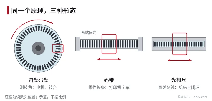
- Circular encoder disc: measures rotation angle; used in servo motors, rotary tables, robot joints and so on.
- Code strip: a flexible strip that measures linear displacement; printer carriages commonly use code strips.
- Linear scale: the lines are made on a straight scale; full closed-loop control on CNC machine tools adds a linear scale in addition to the motor encoder.
There are also several substrates. On glass encoder discs the lines are usually chrome deposited on glass and formed by photolithography and etching, so lines can be very fine and numerous; metal encoder discs are mostly stainless steel and reflective, resistant to shock and vibration; PC discs are light and not fragile, suited to high-volume, low-cost applications.
Summary
The encoder disc is the part of the encoder that carries the “scale”; all position information comes from it. The line count sets the native resolution, line accuracy and concentricity set the basis of accuracy, and line quality determines signal quality. Any evaluation of an encoder ultimately comes back to this one disc.
Translated from the ENC7 Chinese technical library (article 0011). Read the Chinese original. Need a disc built to your drawing? Request a quote or see our custom encoder discs.
© Langfang Jingzheng Optoelectronic Technology Co., Ltd. All rights reserved. This article was created with AI assistance.