Introduction to encoder principles
What Is an Encoder: The Eye That Measures How Far a Machine Turns

A controller knows how far a motor has turned, how fast it is turning and where it has stopped only because of the encoder. Using an odometer and a door handle as analogies, this article explains what an encoder does, the two classifications by sensing principle and by output, and the role of the encoder disc.
When you drive, the odometer on the dashboard tells you how many kilometres you have travelled. It does not “look” at the road; it works out the distance from how many times the wheels have turned. Or think of turning a door handle: you need not look down, because the feel in your hand tells you how far it has been turned.
A machine has no such feel. If a servo motor has turned 37 revolutions plus 90°, or a robot-arm joint has stopped at 120.5°, the controller can know this only through a part whose job is to “watch” rotation: the encoder.
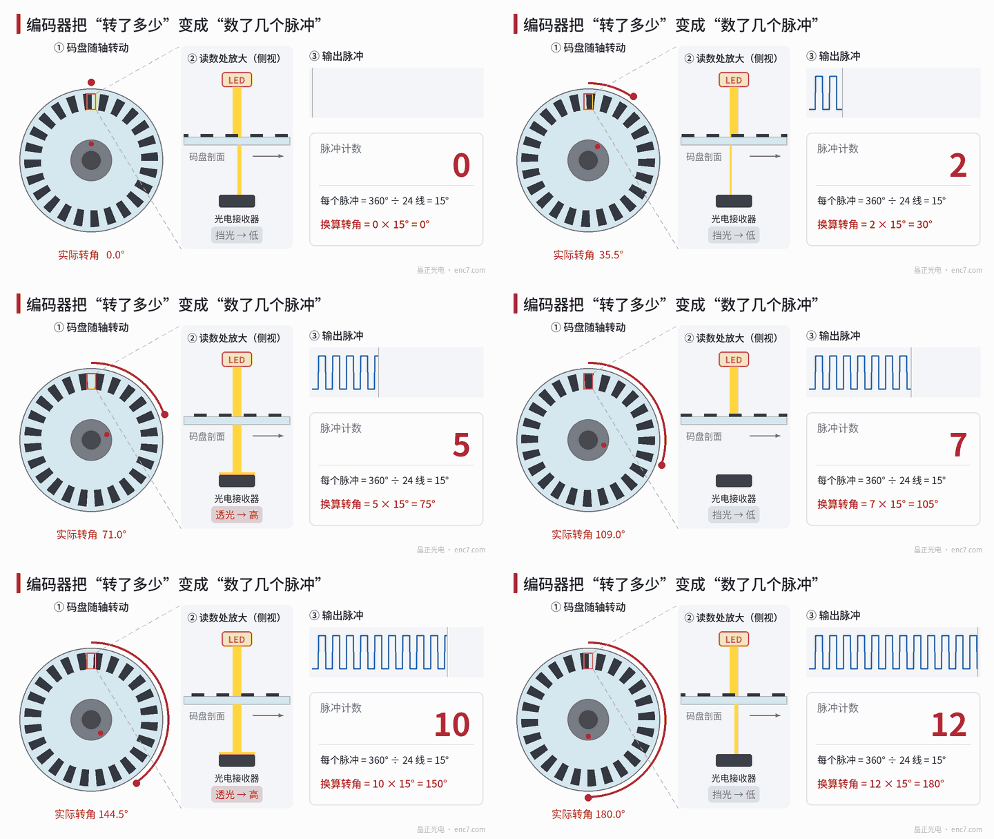
What an encoder does: turning rotation into numbers
Take a common optical encoder as an example; see Figure 1. An encoder disc is mounted on the shaft, with a ring of evenly spaced graduation lines. The lines block light; the gaps between them transmit it. A light source sits on one side of the disc and a photodetector on the other. Each time the disc turns through one line period, the detector outputs one pulse.
The disc in Figure 1 has only 24 lines, so each pulse represents 360° ÷ 24 = 15°. Count 12 pulses and you know it has turned 180°.
Real products have far more lines. A 1000-line disc with fourfold decoding, for example, yields 4000 counts per revolution, so each count is only 0.09°. If the motor drives a table through a leadscrew with a 10 mm lead, and the encoder produces 10 000 counts per revolution, each count corresponds to 1 μm of table travel (ignoring transmission error).
Counting pulses also gives speed: the more pulses in a unit of time, the faster the rotation. So an encoder provides both position and speed feedback.
Classification by principle: light, magnetism, capacitance and electromagnetic induction
There is more than one way to “watch” rotation:
| Type | How rotation is sensed | Typical features |
|---|---|---|
| Optical | Graduation lines on the disc modulate light; a photoelectric element receives it | Lines can be made very fine, so high resolution and accuracy are readily achieved |
| Magnetic | A magnet or a multipole magnetic ring turns with the shaft; a Hall or magnetoresistive element senses the field change | Compact, insensitive to oil and dust |
| Capacitive | Electrode patterns on the rotor and stator move relative to each other, and the capacitance varies periodically | Electrodes can be made on a circuit board; the structure can be very thin |
| Resolver | Electromagnetic induction between windings produces sine and cosine voltages that vary with angle | Temperature- and vibration-tolerant; often used on traction motors in new-energy vehicles |
Each principle has applications it suits; none covers every case. Where high resolution and high accuracy are needed — servos and precision instruments — optical encoders are the usual choice.
Classification by output: incremental and absolute
Another classification looks at what is output; see Figure 2.
- Incremental: only pulses are output, and the controller counts them from some starting point. It is like counting stairs: you know how many steps you have taken, but after a power loss you forget which step you are on and must “home” to a reference on power-up.
- Absolute: the disc has several tracks, and each angle corresponds to a unique code. It is like a house number: whenever you look, you know where you are, and the present position can be read as soon as power is applied.
The two classifications cut across each other: optical encoders come in both incremental and absolute forms, and so do magnetic encoders.
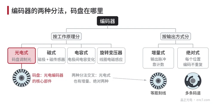
Where the encoder disc sits in the encoder
If an optical encoder is an eye, the encoder disc is the “ruler” it looks at. The light source, the detector and the amplifier/squaring electronics all work on the light-and-dark signal that the disc has already modulated.
So several properties of the disc set the level of the encoder directly: the line count sets how finely it can resolve; whether the lines are in the right place and whether the disc is mounted true sets whether the reading is accurate; whether the line edges are clean, whether the blocking is complete and whether the surface is clean sets whether the signal is good. The substrate matters too: a glass encoder disc is accurate, a metal encoder disc resists shock, and a plastic disc is light and inexpensive — each has its use.
In brief
An encoder is the “eye” with which a machine senses rotation, turning how far and how fast it has turned into numbers a controller can use. By principle there are optical, magnetic, capacitive and resolver types; by output there are incremental and absolute types. In an optical encoder, the encoder disc is the ruler that decides resolution and accuracy.
Translated from the ENC7 Chinese technical library (article 0001). Read the Chinese original. Need a disc built to your drawing? Request a quote or see our custom encoder discs.
© Langfang Jingzheng Optoelectronic Technology Co., Ltd. All rights reserved. This article was created with AI assistance.