Encoder disc basics
What Is on an Encoder Disc? Incremental, Index and Absolute Tracks

The rings of pattern on an encoder disc are called tracks, and each has its own job: the incremental track counts steps, the index track provides a reference, the commutation tracks serve servo motors, absolute tracks read out position directly, and the centring ring helps alignment during assembly. This article introduces each track and compares the patterns of incremental and absolute discs.
Hold an encoder disc up to the light and you see rings of pattern of different fineness: a densely lined outer ring, a few long arcs further in, and one ring with just a single small opening. Each ring is called a “track”, and each has its own job. Recognising the tracks is the first step in reading an encoder disc drawing.
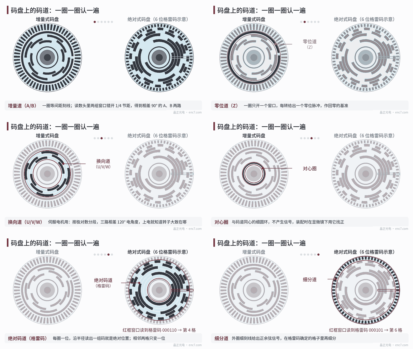
Incremental track: counting “how many steps”
The incremental track is a ring of equally spaced lines; the “line count” of a disc refers to it. A 2500-line disc produces 2500 signal periods per revolution.
Channels A and B come from the same incremental track: the readhead has two sets of windows offset from each other by 1/4 pitch, giving two signals 90° apart, used to detect direction and for x4 decoding.
The incremental track is usually placed on the outer ring because the pitch is p = 2πr ÷ N. For the same line count, the larger the radius, the wider the pitch. 2500 lines at a radius of 20 mm give a pitch of about 50 μm and a line width of about 25 μm; moved to a radius of 10 mm, the pitch is only about 25 μm, which makes both manufacturing and reading harder.
Index track: one landmark per revolution
At power-up an incremental encoder does not know where it is; it can only count from its current position. The index track has a single window per revolution and produces one index pulse (Z) per revolution, which the controller uses as the reference for homing.
The position of the index window must be aligned precisely with the incremental lines so that the Z pulse keeps a fixed phase relationship with signals A and B.
Commutation tracks: for servo motors
After power-up, the drive of a brushless servo motor needs to know roughly where the rotor poles are in order to energise the windings correctly. The commutation tracks exist for this purpose; usually there are three rings, U, V and W.
Each ring is divided into segments according to the number of motor pole pairs, and the three channels are 120° electrical apart. For a motor with 4 pole pairs, each channel goes through 4 cycles per revolution, and the three channels are offset by 120° ÷ 4 = 30° mechanical — see Figure 1. Combined, the three signals have 6 states, each corresponding to 60° electrical, which is enough to get the motor turning; after that, the incremental track takes over precise commutation.
Centring ring and markings
The centring ring is a fine circular ring concentric with the tracks. It produces no signal and is used only for assembly: under a microscope the shaft is rotated and the disc adjusted until the centring ring no longer wobbles. An eccentricity of 5 μm at a radius of 20 mm causes an error of about 52″ with a single readhead, so this step is critical.
Discs also often carry markings such as lot number, direction and pattern-side identification for traceability and assembly.
Absolute discs: one ring per bit
An absolute disc “writes” the position directly onto the disc. The right-hand side of Figure 1 shows 6 rings of Gray code, each representing one bit; reading a set of 0s and 1s along the radius tells which of 64 cells the disc is in, each cell being 360° ÷ 64 = 5.625°.
Gray code is used rather than plain binary because adjacent Gray codes differ in only one bit, so even when the reading window sits on a cell boundary it cannot read a wildly wrong value. The most significant bit is on the inner ring and the finest bit on the outer ring — again because the outer ring has a larger circumference, so the pattern does not become too fine.
For absolute discs with more bits, the usual approach is not to make every bit a separate ring but to determine the coarse position with coded tracks (or a single pseudo-random code track) and then use an outer interpolation track producing sine/cosine signals to interpolate within the cell.
The patterns of the two kinds of disc compare as follows:
| Incremental disc | Absolute disc | |
|---|---|---|
| Main tracks | Incremental track, index track; plus commutation tracks for servo use | Several coded tracks or a pseudo-random code track, plus an interpolation track |
| After power-up | Must turn to the index to know the absolute position | Reads the current position directly |
| Pattern characteristics | Fine lines on the outer ring, simple inner rings | Each ring has a different pattern; more complex layout |
Summary
The incremental track counts steps, the index track provides the reference, the commutation tracks help the motor start, absolute tracks give the position directly, and the centring ring and markings serve assembly and traceability. When reading an encoder disc drawing, first identify which track each ring is, then look at its line count, radius and tolerances, and nothing will be missed.
Translated from the ENC7 Chinese technical library (article 0012). Read the Chinese original. Need a disc built to your drawing? Request a quote or see our custom encoder discs.
© Langfang Jingzheng Optoelectronic Technology Co., Ltd. All rights reserved. This article was created with AI assistance.