Assembly
What the Centring Ring and Marks on an Encoder Disc Are For

Besides the tracks, a disc carries a fine centring ring and a few small marks. The centring ring is concentric with the tracks: during assembly, turning the shaft under a microscope and watching how much it wobbles lets you bring eccentricity within a few microns. Locating, direction, pattern-side and batch marks serve assembly and traceability. This article explains their roles and the centring procedure.
Under a magnifier, besides the rings of tracks you can often see a very fine circle, a small triangle or arrow, and a string of small characters. They produce no signal and the readhead ignores them, yet they bear directly on assembly quality and on whether problems can be traced.
Centring ring: making eccentricity visible
The centring ring is a fine circle concentric with the tracks, made in the same exposure as the tracks, so its centre is the centre of the track pattern. The disc’s OD and bore are cut later and inevitably deviate somewhat from the pattern, so centring on them is less reliable than centring on the ring.
Why care so much about concentricity? Eccentricity produces a once-per-revolution sinusoidal error of amplitude Δθ ≈ e ÷ r. At a read radius of 20 mm:
| Eccentricity e | Angular error (approx.) |
|---|---|
| 1 μm | 10″ |
| 5 μm | 52″ |
| 10 μm | 103″ |
A few microns of eccentricity is invisible to the eye, but under a microscope the swing of the centring ring is obvious.
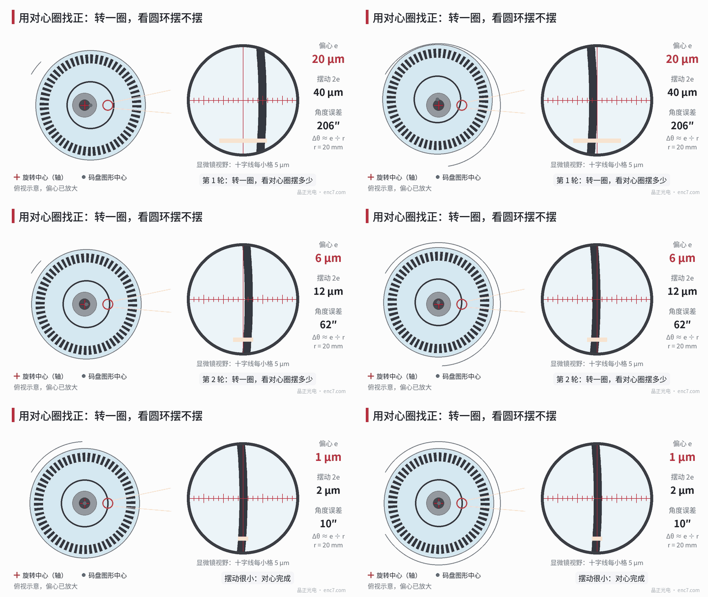
How to centre under a microscope
Typical steps (Figure 1):
- Place the disc on the hub while the adhesive is still uncured, so the disc can still move slightly;
- Aim the microscope at the centring ring, focus, and put the crosshair on the ring edge;
- Slowly turn the shaft a full revolution and see how far the ring swings relative to the crosshair. The swing (peak-to-peak) is about 2e;
- At the position where the ring swings furthest, gently push the disc toward the centre by about half the swing;
- Repeat steps 3 and 4 until the swing is within requirement, then cure the adhesive, and recheck after curing.
Example: read radius 20 mm, required eccentricity error no more than about 10″ — eccentricity must be held to about 1 μm, i.e. a swing in the microscope of no more than about 2 μm. This needs a microscope or vision system with enough magnification and micron-level scale resolution.
Two details are worth noting. First, eccentricity is an offset of the centre and is the same at whatever radius it is measured, so e measured on the centring ring can be used directly to calculate error at the read radius. Second, what this procedure centres is the disc’s eccentricity relative to the actual axis of rotation — exactly the quantity that affects the reading.
Other marks
Besides the centring ring, discs commonly carry the following kinds of marks (Figure 2).
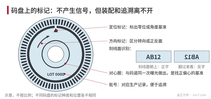
- Locating mark: marks the zero or an angular datum, used during assembly to align with the shaft or motor datum.
- Direction mark: distinguishes rotation direction or front/back to prevent mounting it the wrong way.
- Pattern-side identification: glass is transparent and the pattern is visible from the back. If text reads correctly from the pattern side, it reads mirrored from the other side, so you can tell at a glance which face carries the pattern. If the pattern side faces the wrong way, the read gap changes.
- Batch number: links to production records so that if a problem occurs it can be traced to batch, process and inspection data.
All these marks must be placed outside the tracks so they do not interfere with reading. Which marks a disc carries and where varies from disc to disc, and is generally agreed with the disc manufacturer on the drawing.
Summary
The centring ring is concentric with the tracks and is the datum for removing eccentricity during assembly: turn once and watch the swing, which is about 2e; nudge at the extreme and repeat a few times. Locating, direction, pattern-side and batch marks look insignificant but prevent mis-assembly and aid traceability. Identify these marks first when you receive a disc and assembly goes much more smoothly.
Translated from the ENC7 Chinese technical library (article 0020). Read the Chinese original. Need a disc built to your drawing? Request a quote or see our custom encoder discs.
© Langfang Jingzheng Optoelectronic Technology Co., Ltd. All rights reserved. This article was created with AI assistance.