Testing, reliability & quality
Why Glass Encoder Discs Break: Fracture Mechanics and Edge Defects
The theoretical strength of glass is of GPa order, yet an encoder disc may crack at only a few tens of MPa. This article uses the Griffith criterion σ_f = K_IC/(Y·√(πa)) to relate edge-crack depth to strength, compares the stress levels of rotation, thermal shock and bore thermal mismatch, and explains the roles of static fatigue, chamfering and chemical strengthening.
After assembly a glass encoder disc develops a radial crack at the bore edge, or after one high–low temperature test it shatters from the edge. From atomic-bond calculations the theoretical strength of glass is of order E/10, i.e. several GPa; in practice a few tens of MPa of tensile stress can fracture a disc. The gap comes from defects: microcracks left at the edge by laser cutting, edge grinding and handling set the true strength of that piece of glass.
Griffith criterion and the stress intensity factor
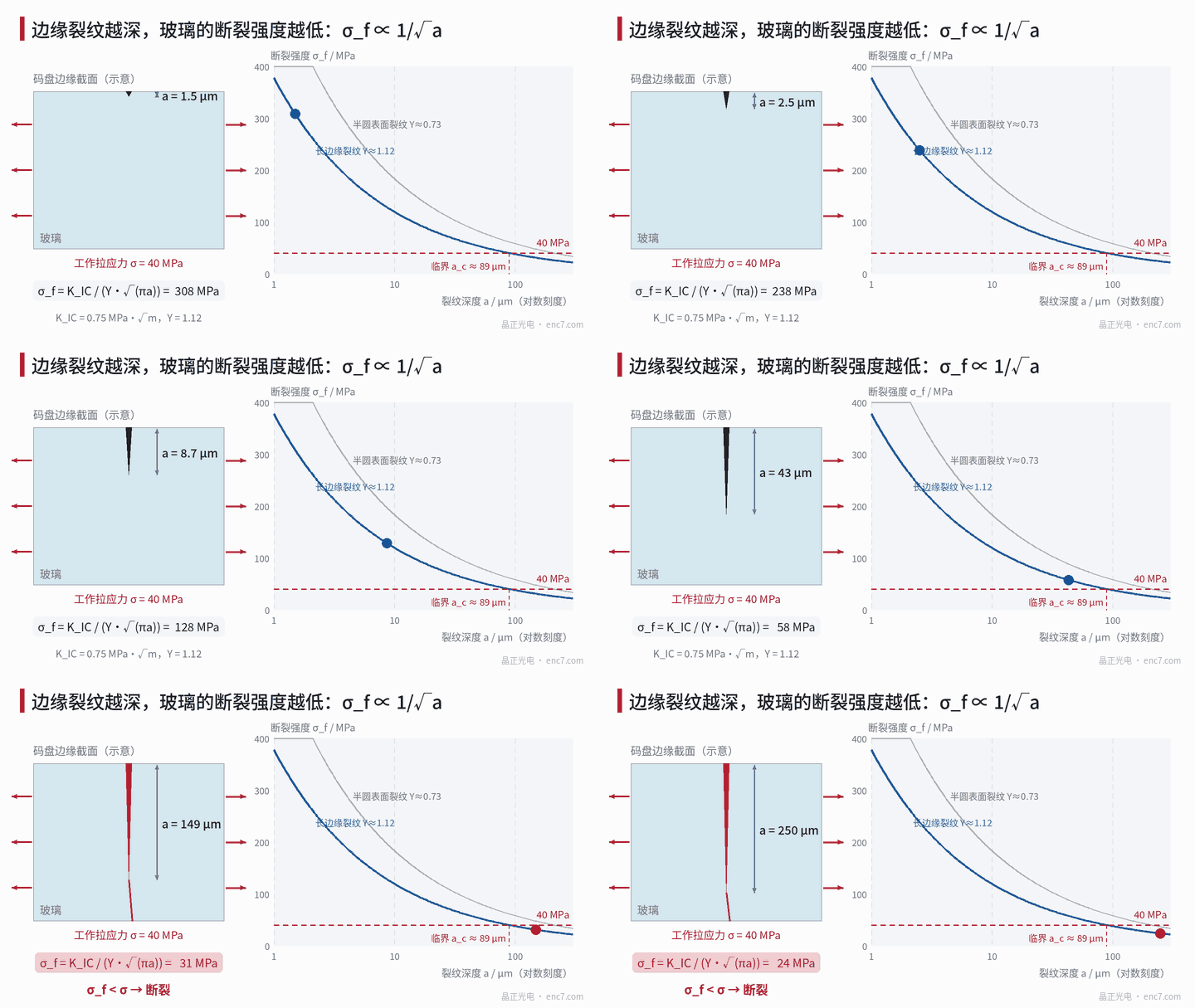
Glass has almost no plasticity; fracture is controlled by the stress field at the crack tip. Linear-elastic fracture mechanics describes that field with the stress intensity factor:
K_I = Y·σ·√(πa)
where σ is the far-field tensile stress, a the crack depth and Y a geometry factor: about 1.12 for a long straight edge crack, about 0.7 at the deepest point of a semi-circular surface crack. When K_I reaches the material’s fracture toughness K_IC the crack grows unstably:
σ_f = K_IC / (Y·√(πa))
This is equivalent to Griffith’s energy criterion: the crack grows when the elastic strain energy released by its advance can supply the energy needed for new surface. Glass has K_IC of about 0.7~0.8 MPa·√m; soda-lime glass is often taken as 0.75.
Worked example: how deep a defect, how low a strength?
Take K_IC = 0.75 MPa·√m:
| Crack depth a | σ_f (Y = 1.12) | σ_f (Y = 0.73) |
|---|---|---|
| 1 μm | 378 MPa | 580 MPa |
| 10 μm | 120 MPa | 183 MPa |
| 20 μm | 85 MPa | 130 MPa |
| 50 μm | 53 MPa | 82 MPa |
| 100 μm | 38 MPa | 58 MPa |
Conversely, for a given working stress σ the critical crack depth is
a_c = (1/π)·[K_IC / (Y·σ)]²
At σ = 40 MPa, a_c ≈ 89 μm; at σ = 80 MPa it is only about 22 μm. Strength scales inversely with √a: reducing the deepest defect from 50 μm to 10 μm raises strength by about a factor of 2.2.
Where does tensile stress on a disc come from?
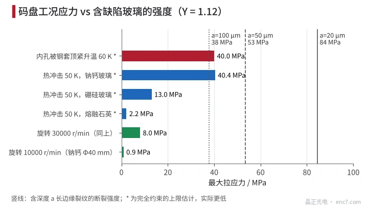
Figure 2 compares the tensile-stress magnitude of several duty cases:
- Rotational centrifugal force: soda-lime glass, OD 40 mm, bore 8 mm; at 10000 r/min the hoop stress at the bore is about 0.9 MPa, at 30000 r/min about 8 MPa. Small discs generally do not fracture from speed alone.
- Thermal shock: for a sudden surface temperature change ΔT the fully constrained upper bound is σ = E·α·ΔT/(1−ν). At ΔT = 50 K, soda-lime glass is about 40 MPa, borosilicate about 13 MPa, fused silica about 2.2 MPa. Real heat transfer is limited so the stress is below the bound, but the material ranking is real.
- Bore thermal mismatch: the bore is tightly constrained by a steel bushing (zero-clearance fit or the bore filled with hard adhesive); on heating, steel expands more than glass and forces the bore outward. Estimating as a large plate with a circular hole under internal pressure, the hoop tensile stress at the bore is about E·Δα·ΔT/(1+ν); borosilicate on stainless steel heated by 60 K gives about 40 MPa.
- Clamping and impact: point contact from a screw clamp plate, or a hard-object collision in a drop, create local high stress and also new surface cracks.
So the real hazards are thermal stress and assembly constraint; together with edge defects they are the main cause of disc cracking.
Time is a variable too: static fatigue
In moist air, water molecules react with the glass network at the crack tip, so a crack can grow slowly even when K_I is below K_IC—stress corrosion or static fatigue. Crack speed is often written v = A·K_I^N; for glass the exponent N is typically in the teens to several tens, depending on glass type and environment.
The corollary: life under constant load is roughly proportional to σ^(−N); halving the stress can extend life by several orders of magnitude, while strength measured under fast loading overestimates long-term load-bearing capacity. For a bore edge that carries assembly prestress for years, the design stress should be well below the short-time strength.
Chamfering, grinding and strengthening
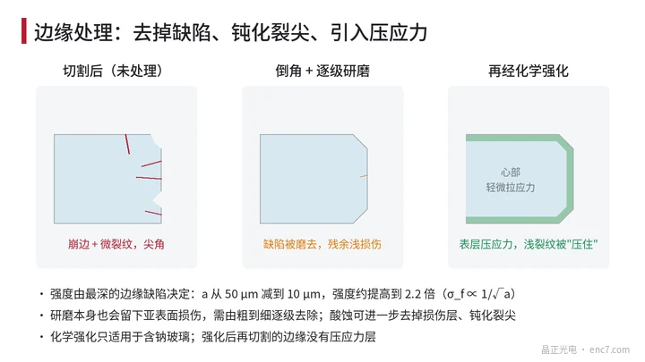
- Chamfering and staged grinding: remove chips and sharp corners. Grinding itself leaves subsurface damage that must be removed stage by stage from coarse to fine; otherwise large defects are merely replaced by medium ones.
- Acid etching: hydrofluoric-acid-type solutions remove the damaged layer and blunt crack tips; strength can rise markedly, but the chrome pattern must be protected.
- Chemical strengthening: in molten potassium nitrate at about 400 ℃, sodium ions in the surface layer of the glass are replaced by larger potassium ions, forming a compressive surface stress tens of micrometres deep and up to several hundred MPa. A crack shallower than the compressive layer must first overcome that compression before it can open. It applies only to sodium-bearing glasses; borosilicate responds weakly and fused silica not at all; and after strengthening, any subsequent cutting of the OD and bore has no compressive layer—process sequence must account for that.
- Structural design: leaving clearance between bore and shaft and using a compliant adhesive, and avoiding point-contact clamping, is more effective than simply raising glass strength.
Engineering points
- Tie visual standards to fracture mechanics: with a bore-edge working-stress upper limit of 40 MPa and a factor of safety of 2, the allowable crack depth at Y = 1.12 is about 22 μm; the chip-depth limit should be set from that.
- Visible chips often have deeper cracks beneath them; limits must be verified by strength tests (ring-on-ring, three-point bend), not by visual size alone.
- Where thermal shock is a risk, prefer a low-expansion substrate: for the same 50 K swing the thermal-stress upper bound is about 40 MPa for soda-lime, about 1/3 of that for borosilicate, and only about 2 MPa for fused silica.
- Do not hard-couple the bore to a steel shaft with zero clearance; a 60 K rise can push the bore-stress upper bound to 40 MPa, comparable to the strength of an 90 μm defect.
- Centrifugal stress at common speeds is only of order 1 MPa; before raising speed, check thermal and assembly stresses first.
- Allow for static fatigue: under long-term load the allowable stress should be well below short-time measured strength, and humidity in service should be controlled.
Summary
The strength of a glass encoder disc is set by its deepest edge defect; σ_f = K_IC/(Y·√(πa)) converts defect depth directly into strength: a defect of a few tens of micrometres corresponds to a few tens of MPa. Hazardous stresses come mainly from thermal shock and bore assembly constraint, not from rotation. Controlling cutting and edge-grinding quality and designing assembly constraints rationally is more effective than chasing a stronger glass.
Translated from the ENC7 Chinese technical library (article 0195). Read the Chinese original. Need a disc built to your drawing? Request a quote or see our custom encoder discs.
© Langfang Jingzheng Optoelectronic Technology Co., Ltd. All rights reserved. This article was created with AI assistance.