Introduction to encoder principles
Why the A and B Signals Are Shifted by 90°
A single pulse train can be counted, but it cannot tell direction. An incremental encoder outputs two A and B signals 90° apart; whichever changes first shows which way the shaft is turning. This article explains the direction-sensing principle, the four-state cycle, and what goes wrong when the phase difference leaves 90°.
On the terminals of an incremental encoder, besides the supply, there are almost always two signal wires A and B. If channel A alone can already count pulses, why is B needed? And why must the two be shifted by 90°?
The answer: one signal can only tell you that something has moved, not which way it moved.
With only one signal, the count will go wrong
Suppose there is only channel A. In one cycle of forward rotation A produces one pulse; in one cycle of reverse rotation A also produces one pulse, and the waveforms look the same. A counter cannot tell them apart and can only increment in both cases.
Worse is jitter at standstill. If the disc happens to stop on the edge of a line, a tiny vibration of the shaft will make A toggle repeatedly, the counter will keep adding, and the position will drift farther and farther.
Shift by ¼ cycle, and direction is hidden in which comes first
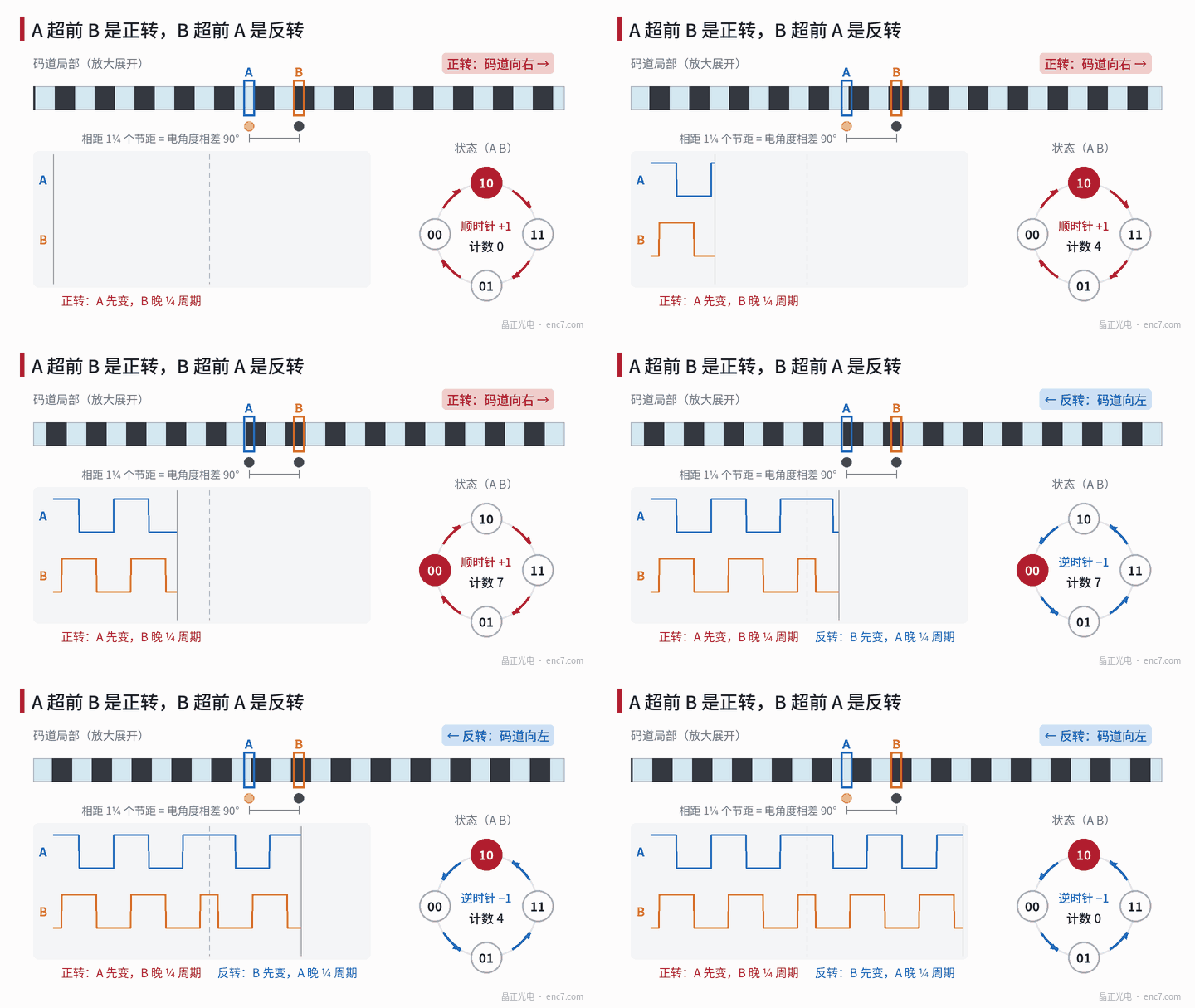
The remedy is to place another window in the readhead and read channel B. The distance between the two windows is not an integer number of pitches, but a quarter-pitch more (for example 1¼ pitches). Then B has the same waveform as A, but is shifted in time by ¼ cycle, that is 90° of electrical angle; see Figure 1.
When the track moves in one direction, the same line edge passes the A window first and the B window later, so A always changes before B — A leads B. When it moves the other way, it passes B first, and B leads A. The direction rule can be very simple:
- On the rising edge of A, look at B: if B is low, A is leading, and the motion is called forward;
- if B is high, B is leading, and the motion is called reverse.
Which direction is called “forward” is a convention of the encoder and is taken from the product documentation.
Four states, one cycle around
Writing the levels of A and B as a two-bit number (A first), 4 states appear in turn in one cycle:
- Forward: 00 → 10 → 11 → 01 → 00
- Reverse: 00 → 01 → 11 → 10 → 00
Only one bit changes between adjacent states. The decoder need only remember the previous state and see whether the next one “goes with the cycle” or “goes against it”, and then add 1 or subtract 1 at each change. The standstill jitter mentioned above then only makes the count go back and forth between two neighbouring values; it does not accumulate.
If both bits change at once, for example from 00 straight to 11, a state has been missed — perhaps the speed was too high or there was interference — and some decoders will report it as an error.
Why it has to be 90°
90° gives each of the 4 states ¼ cycle, all equally wide, and leaves the greatest margin for the later circuit. When the phase difference leaves 90°, two of the states become narrower; see Figure 2.
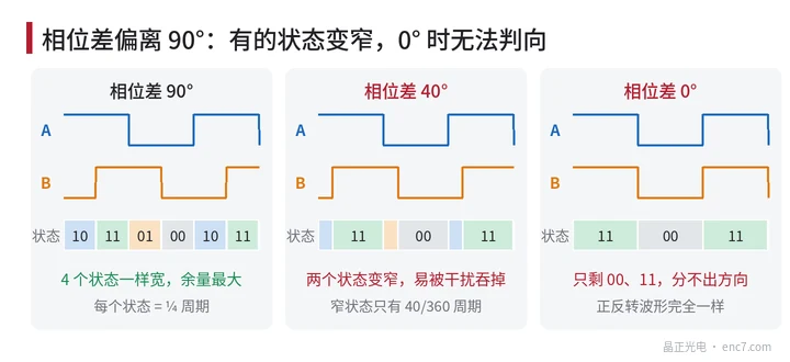
A worked example: a 2500-line encoder at 3000 r/min, that is 50 revolutions per second, has a signal frequency of 2500 × 50 = 125 kHz, so one cycle is 8 μs. At a 90° phase difference each state lasts 2 μs; if the phase difference becomes 40°, the narrow state is only 8 × 40 ÷ 360 ≈ 0.89 μs. Cable delay, filtering and noise can “eat” a state that short, causing lost counts or a wrong direction. At 0° phase difference A and B are fully synchronous, the forward and reverse waveforms are the same, and direction can no longer be told at all.
What decides the phase difference
The 90° between A and B comes from the fit between the spacing of the reading windows and the pitch of the disc. The pitch p = 2πr ÷ N, so a change in reading radius changes the pitch. If the disc is mounted off-centre, or the mounting position departs from the design radius, the actual pitch will not match the design value, the phase difference of A and B will leave 90°, and with eccentricity it will also vary periodically with angle. So the uniformity of the disc lines and the centring accuracy of the mounting all show up in the phase of A and B.
In brief
The A and B signals are shifted by 90° so that direction is hidden in “which changes first”. In forward rotation the states cycle 00→10→11→01; in reverse they run the other way, and each change adds or subtracts 1. 90° makes the 4 states equally wide and leaves the greatest margin; the farther the departure, the easier it is to go wrong.
Translated from the ENC7 Chinese technical library (article 0003). Read the Chinese original. Need a disc built to your drawing? Request a quote or see our custom encoder discs.
© Langfang Jingzheng Optoelectronic Technology Co., Ltd. All rights reserved. This article was created with AI assistance.