Industry applications in depth
Worm-Gear Tables: Full Closed Loop with a Large Encoder Disc
The motor-end encoder on a worm-gear rotary table measures the worm angle; the worm-wheel pitch and the meshing backlash both lie outside its field of view. Using example parameters, this article computes a semi-closed-loop U of about 22″ and a fully closed-loop value of about 1.9″, and gives the line-count, dual-readhead and dual-loop control points for a Ø200 mm encoder disc.
A worm-gear rotary table trades a large reduction ratio for high torque and self-locking, and the cost is low as well. The usual practice is to mount the encoder at the rear of the motor (semi-closed loop): 90 revolutions of the motor turn the table through 1 revolution, and the table angle is inferred by dividing the motor angle by 90. The encoder itself is accurate; the problem is that what it measures is not the table.
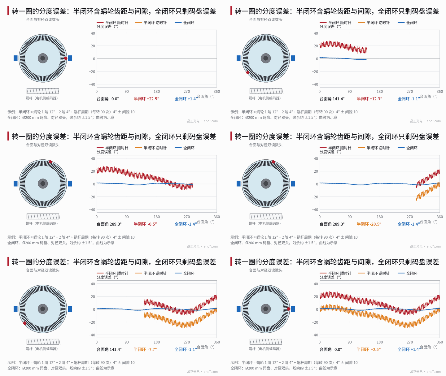
What the semi-closed loop actually measures
Actual table angle = motor angle ÷ i + transmission-chain error, i = 90. The transmission-chain error includes:
- Worm-wheel pitch error: mounting eccentricity and machining error of the worm wheel produce 1 and 2 undulations per table revolution, usually the largest term;
- Worm periodic error: it repeats once per worm revolution, and therefore 90 times per table revolution;
- Meshing backlash: the table stops at a different position depending on the direction of approach;
- Elastic and thermal deformation: axial play and torsional elasticity of the worm, and the effect of temperature on the centre distance.
The error of the motor encoder itself is divided by 90: ±60″ is left as only 0.67″. Resolution is even less of a problem: a 23-bit encoder referred to the table is 360° × 3600 ÷ (2²³ × 90) = 0.0017″ per count. The bottleneck of the semi-closed loop is not the quality of the encoder, but the transmission chain.
Full closed loop: mount the encoder disc on the table
A Ø200 mm encoder disc is mounted on the table rotor. Taking the reading radius as r = 95 mm, 1 μm of eccentricity corresponds to 1 μm ÷ 95 mm = 2.17″, and 2 μm is 4.34″. With two readheads placed diametrically opposite, averaging the readings at both ends cancels eccentricity and the other odd-order errors almost completely; taking the residual as 5% (an example assumption) gives 0.22″ (Figure 3). The table lists the standard uncertainty of each term, with sinusoidal components taken as amplitude ÷ √2 and uniform distributions as half-width ÷ √3:
| Error source (example) | Semi-closed loop | Full closed loop |
|---|---|---|
| Worm wheel, 1st order (amplitude 12″) | 8.49″ | corrected by feedback |
| Worm wheel, 2nd order (4″) | 2.83″ | corrected by feedback |
| Worm periodic error (4″) | 2.83″ | corrected by feedback |
| Backlash (±10″) | 5.77″ | inside the loop |
| Motor encoder ±60″ ÷ 90 | 0.38″ | — |
| Disc graduation, 2nd and 4th order (1.2″, 0.5″) | — | 0.85″, 0.35″ |
| Eccentricity residual 5%, interpolation, quantization noise | — | 0.15″, 0.08″, 0.13″ |
| Combined u_c / expanded U (k = 2) | 11.0″ / 22.0″ | 0.94″ / 1.9″ |
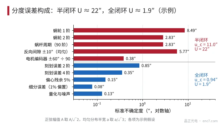
Full closed loop does not make the worm wheel more accurate; it makes the position loop use the table angle directly: whatever extra or short travel the worm wheel produces, the motor makes up the same amount, so the error after arrival is determined by the encoder disc. This conclusion holds for the static position after arrival; during motion, worm periodic error whose frequency lies above the position-loop bandwidth will still appear as speed ripple.
Line count, interpolation and number of readheads
A large-diameter encoder disc need not chase a high line count: take 18 000 lines, and the pitch is 2π × 95 mm ÷ 18 000 = 33.2 μm; with 256-fold interpolation there are 4 608 000 counts per revolution (about 22 bits), 0.28″ per count, and at a table speed of 60 r/min the signal frequency is only 18 kHz. The interpolation error caused by a 1% signal offset is 72″ × 0.01 ÷ 2π = 0.11″. The large pitch also gives a more generous read-gap tolerance; if a diffraction-imaging type of readhead is used, the p²/λ scale is about 1.2 mm (estimated with λ taken as 0.9 μm; the gap tolerance of the chosen readhead is the one that applies).
Number of readheads: averaging N equally spaced readheads leaves only error orders that are integer multiples of N. 2 heads leave the 2nd and 4th orders, and the example U is 1.9″; 4 heads leave the 4th and 8th orders, and with the same set of example data U is about 0.8″, at the cost of more readheads, brackets and centring adjustments. If the positioning target is in the range of a few arcseconds, 2 heads are usually enough.
Dual-loop control: backlash inside the loop
- Use the motor-end encoder for the velocity loop and the table encoder for the position loop: the motor-end signal has neither backlash nor worm elasticity, and suits a high-bandwidth velocity loop; if the position loop contains backlash and compliance, the phase margin falls, and near the stopping point a hunting motion of amplitude comparable to the backlash (a limit cycle) may appear.
- Reduce nonlinearity inside the loop: preload the worm, or take up the backlash with a dual-lead worm; set the position-loop bandwidth at a fraction of the mechanical resonance frequency (a common rule of thumb is about 1/3, which must be confirmed by measurement), and limit the integral action at low speed.
- Deviation monitoring: take the difference between motor angle ÷ i and table angle as a diagnostic quantity. Its normal value lies within the envelope of the transmission error and the backlash (about ±40″ in the example); exceeding the limit indicates coupling slip, a loose encoder disc, or an encoder fault.
Mounting and alternative approaches
- Fix the encoder disc directly to the table rotor or the spindle flange. Mounting through a slender shaft or a coupling brings torsional elasticity into the measurement, which is then no longer the table angle.
- Fix the readhead to the non-rotating base, and adjust the gap and run-out according to the readhead instructions. Thermal drift of the bracket likewise becomes an error; the usual practice on direct-drive rotary tables can be found in a related article in this library.
- If the structure is not to be changed, a semi-closed-loop indexing compensation table can be used: measure one revolution with a reference standard and write the repeatable worm-wheel error into the compensation table. It can compensate only the repeatable part; backlash, and errors that change with temperature, wear and lubrication, remain.
Engineering points
- First decide where the error is: a motor-end encoder referred to the table is only a few tenths of an arcsecond; the error of the semi-closed loop comes from the worm wheel, the worm and the backlash, with an example U of about 22″.
- When the table accuracy requirement is tighter than what the semi-closed loop can deliver (22″ in the example), consider full closed loop: a Ø200 mm encoder disc and diametrically opposed dual heads, with an example U of about 1.9″.
- Choose the line count from the pitch and the signal quality; 18 000 lines × 256 interpolation is about 0.28″, the signal frequency is low, and there is no need to chase a higher line count.
- Averaging the readings at both ends removes the odd orders; 4 heads also remove the 2nd order. Encoder-disc eccentricity is about 2.2″ per 1 μm, and eccentricity must be measured after assembly.
- Put the velocity loop at the motor end and the position loop at the table end, monitor the difference between the two channels, and if backlash is inside the loop, apply preload and limit the integral action.
- Mount the encoder disc directly on the table, not through a coupling or a slender shaft.
In brief
Semi-closed loop on a worm-gear rotary table leaves the error in the transmission chain: worm-wheel pitch, worm periodic error and backlash together take the example indexing uncertainty to 22″, however accurate the motor encoder may be, it cannot see them. Mounting a Ø200 mm encoder disc on the table and using diametrically opposed dual readheads brings the same table down to about 1.9″. What then follows is a stability problem caused by backlash inside the loop, which must be handled by preload, by placing the velocity and position loops separately, and by deviation monitoring.
Translated from the ENC7 Chinese technical library (article 0767). Read the Chinese original. Need a disc built to your drawing? Request a quote or see our custom encoder discs.
© Langfang Jingzheng Optoelectronic Technology Co., Ltd. All rights reserved. This article was created with AI assistance.