Reflective · Stainless steel
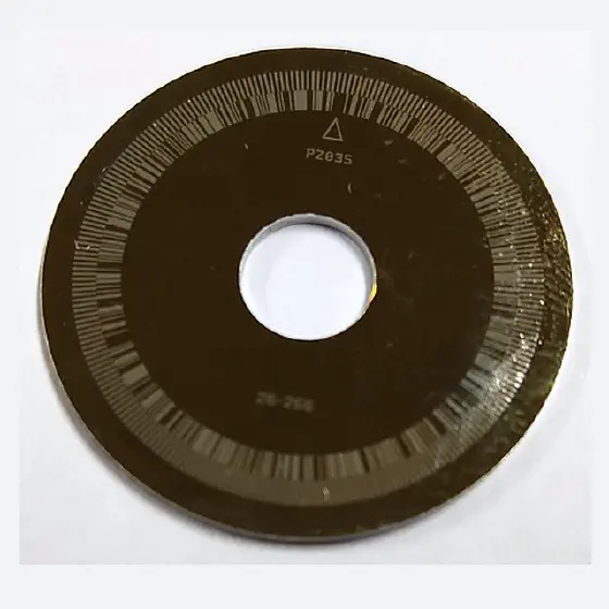
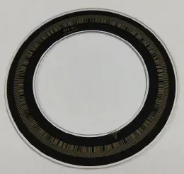
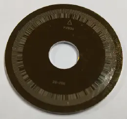
Reflective metal encoder disc
A reflective metal encoder disc is a code wheel on a metal substrate such as stainless steel, patterned by photolithography into high-reflectance and low-reflectance areas. The light source and detector sit on the same side of the disc and read position from the reflected light/dark difference — so the encoder can be built thinner, and the metal disc will not shatter.
Also searched as: reflective encoder disk · stainless steel code wheel · metal codewheel · reflective code disc · steel encoder wheel
- Metal substrate (stainless steel and others) — high strength, shock-resistant
- Reflective optical path — compact, thin encoder designs
- Precise photolithographic high/low-reflectance pattern with clear contrast
- Patented reflective/absorbing film structure (CN217210914U)
- Incremental and absolute patterns; 100% AOI inspected
Specifications
Values marked [spec TBD] are being finalized. Exact figures depend on your drawing — ask for the current datasheet.
| Parameter | Reflective Metal Encoder Disc |
|---|---|
| Substrate | Stainless steel and other metals — grades [spec TBD] |
| Optical path | Reflective (light source and detector on the same side) |
| Encoding | Incremental · Absolute |
| Pattern process | Photolithographic patterning forming high- and low-reflectance areas |
| Reflective film (patent CN217210914U) | Reflectance >90% at 460 nm and 850 nm; absorbing film <1% — per patent text; production values per datasheet [spec TBD] |
| Contour machining | Laser OD cutting · laser bore machining |
| Outer diameter range | [spec TBD] |
| Bore range | [spec TBD] |
| Thickness | [spec TBD] |
| Line count range | [spec TBD] |
| Minimum line width / tolerance | [spec TBD] |
| Pattern-to-bore concentricity | [spec TBD] |
| Operating temperature | [spec TBD] |
| Inspection | 100% AOI machine vision; vision measuring machine; optical testing |
| Capacity | About 30,000 discs per day (all product lines combined) |
What we can customize
- Outer diameter, bore and thickness to drawing
- Line count and track pattern, incremental or absolute
- Reflective and absorbing film layers matched to your readhead wavelength (e.g. 460 nm or 850 nm)
- High- and low-reflectance requirements specified separately
- Hollow-shaft / large-bore designs [TBD: confirm limits]
Ordering information
| Quotation | Engineer reviews your drawing for manufacturability, then quotes with sample and production lead times |
|---|---|
| Minimum order quantity (MOQ) | [TBD: MOQ] |
| Sample lead time | [TBD: sample lead time] |
| Production lead time | [TBD: production lead time] |
| Packaging | [TBD: packaging standard] |
| Trade terms / payment | [TBD: Incoterms and payment terms] |
| Inspection documents | [TBD: inspection report contents shipped with each lot] |
Typical applications
How a reflective disc works
The readhead illuminates the disc and receives the reflected light from the same side. High-reflectance areas return most of the light; low-reflectance areas absorb it. The larger the difference, the larger the signal amplitude, the better the signal-to-noise ratio and the smaller the interpolation error.
Common structures:
- Mirror-finish metal substrate + absorbing film, with the absorbing film removed from the high-reflectance areas by photolithography and etching
- Absorbing substrate + reflective film, with the reflective film removed from the low-reflectance areas
- Reflective film and absorbing film stacked on a substrate, then patterned — the approach used in our patent CN217210914U
Design notes
- Wavelength matters. Reflectance differs between 850 nm infrared and 460 nm blue readheads — tell us which one you use.
- Uniformity matters as much as average. Reflectance fluctuating around the revolution makes amplitude fluctuate and increases interpolation error.
- Readhead gap. Reflective readheads are gap-sensitive; check how shaft and housing expansion change the gap over your temperature range.
Glass vs. reflective metal vs. PC encoder discs
| Criterion | Glass (chrome on glass) | Reflective metal | PC (polycarbonate) |
|---|---|---|---|
| Typical optical path | Transmissive | Reflective (source and detector on the same side) | Transmissive |
| High line counts / absolute multi-track | Easiest | Possible, limited by etching and coating | Moderate resolution |
| Thermal expansion (approx.) | Low — about 3.3 (borosilicate) to 9 (soda-lime) ×10⁻⁶/K | Higher — stainless steel about 16–17 ×10⁻⁶/K | Highest — about 65–70 ×10⁻⁶/K |
| Shock and vibration | Sensitive to drops and impact | Very good — does not shatter | Good — tough, not brittle |
| Encoder height | Needs space on both sides | Can be very thin | Needs space on both sides |
| Relative cost | Higher | Lower than glass | Lowest |
| Best for | CNC, rotary tables, metrology, high-resolution servo | Robot joints, slim servo motors, hollow-shaft encoders | High-volume, cost- and weight-sensitive encoders |
Full comparison: Reflective metal or glass encoder disc? How to choose
Quality control on every disc
- 100% AOI — automated optical inspection of graduation integrity, pitch and surface defects (scratches, spots, chips).
- Vision measuring machine — critical dimensions such as outer diameter, bore and pattern-to-bore concentricity are verified.
- Optical density testing — transparent and opaque areas are measured on transmissive discs.
- ISO 9001 quality management system, certified since 2012.
Frequently asked questions
When should I use a reflective metal disc instead of glass?
What determines the signal strength of a reflective encoder disc?
What should I specify for a reflective disc RFQ?
What does patent CN217210914U cover?
Downloads
- Reflective Metal Encoder Disc datasheet (PDF) — [TBD: datasheet file] · available on request now: sales@enc7.com
- RFQ checklist: 20 parameters to send with your drawing
Last updated 1 January 0001 · ENC7 Engineering Team